

2 A Path to the Blended Junction
33
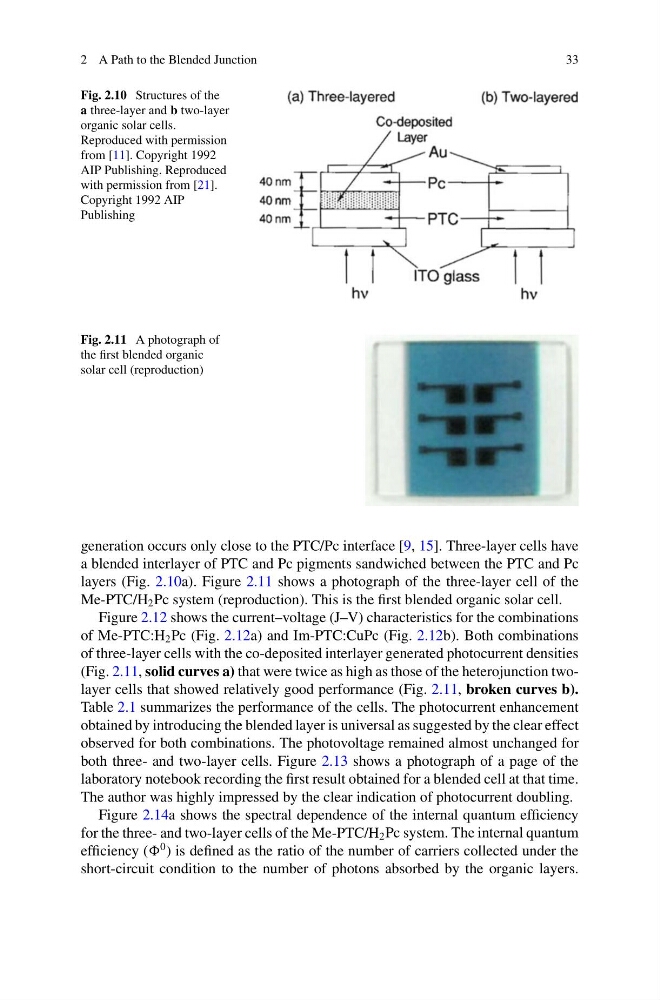
Fig. 2.10 Structures of the
a three-layer and b two-layer
organic solar cells.
Reproduced with permission
from [11]. Copyright 1992
AIP Publishing. Reproduced
with permission from [21].
Copyright 1992 AIP
Publishing
Fig. 2.11 A photograph of
the first blended organic
solar cell (reproduction)
generation occurs only close to the PTC/Pc interface [9, 15]. Three-layer cells have
a blended interlayer of PTC and Pc pigments sandwiched between the PTC and Pc
layers (Fig. 2.10a). Figure 2.11 shows a photograph of the three-layer cell of the
Me-PTC/H 2 Pc system (reproduction). This is the first blended organic solar cell.
Figure 2.12 shows the current–voltage (J–V) characteristics for the combinations
of Me-PTC:H 2 Pc (Fig. 2.12a) and Im-PTC:CuPc (Fig. 2.12b). Both combinations
of three-layer cells with the co-deposited interlayer generated photocurrent densities
(Fig. 2.11, solid curves a) that were twice as high as those of the heterojunction twolayer cells that showed relatively good performance (Fig. 2.11, broken curves b).
Table 2.1 summarizes the performance of the cells. The photocurrent enhancement
obtained by introducing the blended layer is universal as suggested by the clear effect
observed for both combinations. The photovoltage remained almost unchanged for
both three- and two-layer cells. Figure 2.13 shows a photograph of a page of the
laboratory notebook recording the first result obtained for a blended cell at that time.
The author was highly impressed by the clear indication of photocurrent doubling.
Figure 2.14a shows the spectral dependence of the internal quantum efficiency
for the three- and two-layer cells of the Me-PTC/H 2 Pc system. The internal quantum
efficiency (
0 ) is defined as the ratio of the number of carriers collected under the
short-circuit condition to the number of photons absorbed by the organic layers.
33
Fig. 2.10 Structures of the
a three-layer and b two-layer
organic solar cells.
Reproduced with permission
from [11]. Copyright 1992
AIP Publishing. Reproduced
with permission from [21].
Copyright 1992 AIP
Publishing
Fig. 2.11 A photograph of
the first blended organic
solar cell (reproduction)
generation occurs only close to the PTC/Pc interface [9, 15]. Three-layer cells have
a blended interlayer of PTC and Pc pigments sandwiched between the PTC and Pc
layers (Fig. 2.10a). Figure 2.11 shows a photograph of the three-layer cell of the
Me-PTC/H 2 Pc system (reproduction). This is the first blended organic solar cell.
Figure 2.12 shows the current–voltage (J–V) characteristics for the combinations
of Me-PTC:H 2 Pc (Fig. 2.12a) and Im-PTC:CuPc (Fig. 2.12b). Both combinations
of three-layer cells with the co-deposited interlayer generated photocurrent densities
(Fig. 2.11, solid curves a) that were twice as high as those of the heterojunction twolayer cells that showed relatively good performance (Fig. 2.11, broken curves b).
Table 2.1 summarizes the performance of the cells. The photocurrent enhancement
obtained by introducing the blended layer is universal as suggested by the clear effect
observed for both combinations. The photovoltage remained almost unchanged for
both three- and two-layer cells. Figure 2.13 shows a photograph of a page of the
laboratory notebook recording the first result obtained for a blended cell at that time.
The author was highly impressed by the clear indication of photocurrent doubling.
Figure 2.14a shows the spectral dependence of the internal quantum efficiency
for the three- and two-layer cells of the Me-PTC/H 2 Pc system. The internal quantum
efficiency (
0 ) is defined as the ratio of the number of carriers collected under the
short-circuit condition to the number of photons absorbed by the organic layers.