

32
M. Hiramoto
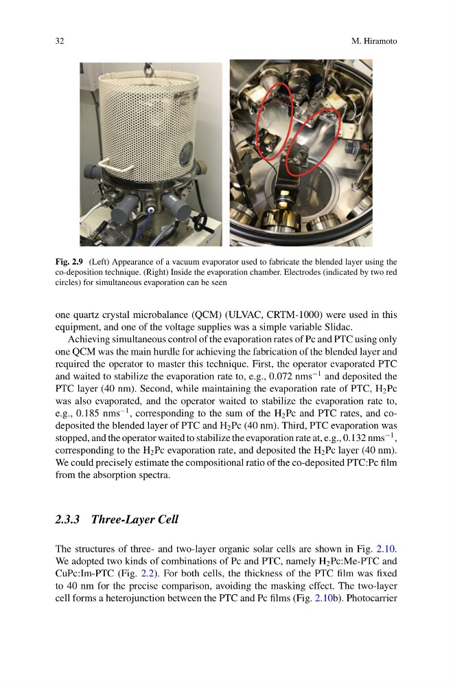
Fig. 2.9 (Left) Appearance of a vacuum evaporator used to fabricate the blended layer using the
co-deposition technique. (Right) Inside the evaporation chamber. Electrodes (indicated by two red
circles) for simultaneous evaporation can be seen
one quartz crystal microbalance (QCM) (ULVAC, CRTM-1000) were used in this
equipment, and one of the voltage supplies was a simple variable Slidac.
Achieving simultaneous control of the evaporation rates of Pc and PTC using only
one QCM was the main hurdle for achieving the fabrication of the blended layer and
required the operator to master this technique. First, the operator evaporated PTC
and waited to stabilize the evaporation rate to, e.g., 0.072 nms
−1 and deposited the
PTC layer (40 nm). Second, while maintaining the evaporation rate of PTC, H 2 Pc
was also evaporated, and the operator waited to stabilize the evaporation rate to,
e.g., 0.185 nms
−1 , corresponding to the sum of the H 2 Pc and PTC rates, and codeposited the blended layer of PTC and H 2 Pc (40 nm). Third, PTC evaporation was
stopped, and the operator waited to stabilize the evaporation rate at, e.g., 0.132 nms
−1 ,
corresponding to the H 2 Pc evaporation rate, and deposited the H 2 Pc layer (40 nm).
We could precisely estimate the compositional ratio of the co-deposited PTC:Pc film
from the absorption spectra.
2.3.3 Three-Layer Cell
The structures of three- and two-layer organic solar cells are shown in Fig. 2.10.
We adopted two kinds of combinations of Pc and PTC, namely H 2 Pc:Me-PTC and
CuPc:Im-PTC (Fig. 2.2). For both cells, the thickness of the PTC film was fixed
to 40 nm for the precise comparison, avoiding the masking effect. The two-layer
cell forms a heterojunction between the PTC and Pc films (Fig. 2.10b). Photocarrier
M. Hiramoto
Fig. 2.9 (Left) Appearance of a vacuum evaporator used to fabricate the blended layer using the
co-deposition technique. (Right) Inside the evaporation chamber. Electrodes (indicated by two red
circles) for simultaneous evaporation can be seen
one quartz crystal microbalance (QCM) (ULVAC, CRTM-1000) were used in this
equipment, and one of the voltage supplies was a simple variable Slidac.
Achieving simultaneous control of the evaporation rates of Pc and PTC using only
one QCM was the main hurdle for achieving the fabrication of the blended layer and
required the operator to master this technique. First, the operator evaporated PTC
and waited to stabilize the evaporation rate to, e.g., 0.072 nms
−1 and deposited the
PTC layer (40 nm). Second, while maintaining the evaporation rate of PTC, H 2 Pc
was also evaporated, and the operator waited to stabilize the evaporation rate to,
e.g., 0.185 nms
−1 , corresponding to the sum of the H 2 Pc and PTC rates, and codeposited the blended layer of PTC and H 2 Pc (40 nm). Third, PTC evaporation was
stopped, and the operator waited to stabilize the evaporation rate at, e.g., 0.132 nms
−1 ,
corresponding to the H 2 Pc evaporation rate, and deposited the H 2 Pc layer (40 nm).
We could precisely estimate the compositional ratio of the co-deposited PTC:Pc film
from the absorption spectra.
2.3.3 Three-Layer Cell
The structures of three- and two-layer organic solar cells are shown in Fig. 2.10.
We adopted two kinds of combinations of Pc and PTC, namely H 2 Pc:Me-PTC and
CuPc:Im-PTC (Fig. 2.2). For both cells, the thickness of the PTC film was fixed
to 40 nm for the precise comparison, avoiding the masking effect. The two-layer
cell forms a heterojunction between the PTC and Pc films (Fig. 2.10b). Photocarrier