

5 Polymer Solar Cells: Development of π-Conjugated Polymers …
107
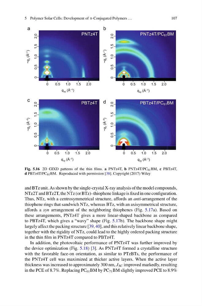
Fig. 5.16 2D GIXD patterns of the thin films. a PNTz4T, b PNTz4T/PC 61 BM, c PBTz4T,
d PBTz4T/PC 61 BM. Reproduced with permission [38]. Copyright (2017) Wiley
and BTz unit. As shown by the single-crystal X-ray analysis of the model compounds,
NTz2T and BTz2T, the NTz (or BTz)–thiophene linkage is fixed in one configuration.
Thus, NTz, with a centrosymmetrical structure, affords an anti-arrangement of the
thiophene rings that sandwich NTz, whereas BTz, with an axisymmetrical structure,
affords a syn arrangement of the neighboring thiophenes (Fig. 5.17a). Based on
these arrangements, PNTz4T gives a more linear-shaped backbone as compared
to PBTz4T, which gives a “wavy” shape (Fig. 5.17b). The backbone shape might
largely affect the packing structure [39, 40], and this relatively linear backbone shape,
together with the rigidity of NTz, could lead to the highly ordered packing structure
in the thin film in PNTz4T compared to PBTz4T.
In addition, the photovoltaic performance of PNTz4T was further improved by
the device optimization (Fig. 5.18) [3]. As PNTz4T formed a crystalline structure
with the favorable face-on orientation, as similar to PTzBTs, the performance of
the PNTz4T cell was maximized at thicker active layers. When the active layer
thickness was increased to approximately 300 nm, J SC improved markedly, resulting
in the PCE of 8.7%. Replacing PC 61 BM by PC 71 BM slightly improved PCE to 8.9%
107
Fig. 5.16 2D GIXD patterns of the thin films. a PNTz4T, b PNTz4T/PC 61 BM, c PBTz4T,
d PBTz4T/PC 61 BM. Reproduced with permission [38]. Copyright (2017) Wiley
and BTz unit. As shown by the single-crystal X-ray analysis of the model compounds,
NTz2T and BTz2T, the NTz (or BTz)–thiophene linkage is fixed in one configuration.
Thus, NTz, with a centrosymmetrical structure, affords an anti-arrangement of the
thiophene rings that sandwich NTz, whereas BTz, with an axisymmetrical structure,
affords a syn arrangement of the neighboring thiophenes (Fig. 5.17a). Based on
these arrangements, PNTz4T gives a more linear-shaped backbone as compared
to PBTz4T, which gives a “wavy” shape (Fig. 5.17b). The backbone shape might
largely affect the packing structure [39, 40], and this relatively linear backbone shape,
together with the rigidity of NTz, could lead to the highly ordered packing structure
in the thin film in PNTz4T compared to PBTz4T.
In addition, the photovoltaic performance of PNTz4T was further improved by
the device optimization (Fig. 5.18) [3]. As PNTz4T formed a crystalline structure
with the favorable face-on orientation, as similar to PTzBTs, the performance of
the PNTz4T cell was maximized at thicker active layers. When the active layer
thickness was increased to approximately 300 nm, J SC improved markedly, resulting
in the PCE of 8.7%. Replacing PC 61 BM by PC 71 BM slightly improved PCE to 8.9%