

106
I. Osaka
N
S
N
N
S
N
S
S
S
C 10 H 21
C 12 H 25
C 10 H 21
C 12 H 25
n
S
N
S
N
S
S
S
C 8 H 17
C 10 H 21
C 8 H 17
C 10 H 21
n
S
PNTz4T
PBTz4T
-15
-10
-5
0
5
-0.2
0
0.2
0.4
0.6
0.8
1
PNTz4T/PC 61 BM
PBTz4T/PC 61 BM
Current density (mA/cm
2
)
Voltage (V)
300 400 500 600 700 800 900
PNTz4T
PBTz4T
Absorbance (a.u.)
Wavelength (nm)
a
c
b
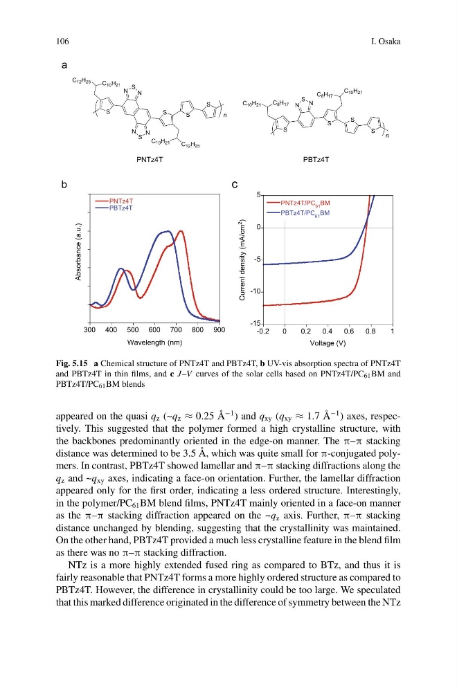
Fig. 5.15 a Chemical structure of PNTz4T and PBTz4T, b UV-vis absorption spectra of PNTz4T
and PBTz4T in thin films, and c J–V curves of the solar cells based on PNTz4T/PC 61 BM and
PBTz4T/PC 61 BM blends
appeared on the quasi q z (~q z ≈ 0.25 Å
−1 ) and q xy (q xy ≈ 1.7 Å
−1 ) axes, respectively. This suggested that the polymer formed a high crystalline structure, with
the backbones predominantly oriented in the edge-on manner. The π–π stacking
distance was determined to be 3.5 Å, which was quite small for π-conjugated polymers. In contrast, PBTz4T showed lamellar and π–π stacking diffractions along the
q z and ~q xy axes, indicating a face-on orientation. Further, the lamellar diffraction
appeared only for the first order, indicating a less ordered structure. Interestingly,
in the polymer/PC 61 BM blend films, PNTz4T mainly oriented in a face-on manner
as the π–π stacking diffraction appeared on the ~q z axis. Further, π–π stacking
distance unchanged by blending, suggesting that the crystallinity was maintained.
On the other hand, PBTz4T provided a much less crystalline feature in the blend film
as there was no π–π stacking diffraction.
NTz is a more highly extended fused ring as compared to BTz, and thus it is
fairly reasonable that PNTz4T forms a more highly ordered structure as compared to
PBTz4T. However, the difference in crystallinity could be too large. We speculated
that this marked difference originated in the difference of symmetry between the NTz
I. Osaka
N
S
N
N
S
N
S
S
S
C 10 H 21
C 12 H 25
C 10 H 21
C 12 H 25
n
S
N
S
N
S
S
S
C 8 H 17
C 10 H 21
C 8 H 17
C 10 H 21
n
S
PNTz4T
PBTz4T
-15
-10
-5
0
5
-0.2
0
0.2
0.4
0.6
0.8
1
PNTz4T/PC 61 BM
PBTz4T/PC 61 BM
Current density (mA/cm
2
)
Voltage (V)
300 400 500 600 700 800 900
PNTz4T
PBTz4T
Absorbance (a.u.)
Wavelength (nm)
a
c
b
Fig. 5.15 a Chemical structure of PNTz4T and PBTz4T, b UV-vis absorption spectra of PNTz4T
and PBTz4T in thin films, and c J–V curves of the solar cells based on PNTz4T/PC 61 BM and
PBTz4T/PC 61 BM blends
appeared on the quasi q z (~q z ≈ 0.25 Å
−1 ) and q xy (q xy ≈ 1.7 Å
−1 ) axes, respectively. This suggested that the polymer formed a high crystalline structure, with
the backbones predominantly oriented in the edge-on manner. The π–π stacking
distance was determined to be 3.5 Å, which was quite small for π-conjugated polymers. In contrast, PBTz4T showed lamellar and π–π stacking diffractions along the
q z and ~q xy axes, indicating a face-on orientation. Further, the lamellar diffraction
appeared only for the first order, indicating a less ordered structure. Interestingly,
in the polymer/PC 61 BM blend films, PNTz4T mainly oriented in a face-on manner
as the π–π stacking diffraction appeared on the ~q z axis. Further, π–π stacking
distance unchanged by blending, suggesting that the crystallinity was maintained.
On the other hand, PBTz4T provided a much less crystalline feature in the blend film
as there was no π–π stacking diffraction.
NTz is a more highly extended fused ring as compared to BTz, and thus it is
fairly reasonable that PNTz4T forms a more highly ordered structure as compared to
PBTz4T. However, the difference in crystallinity could be too large. We speculated
that this marked difference originated in the difference of symmetry between the NTz