

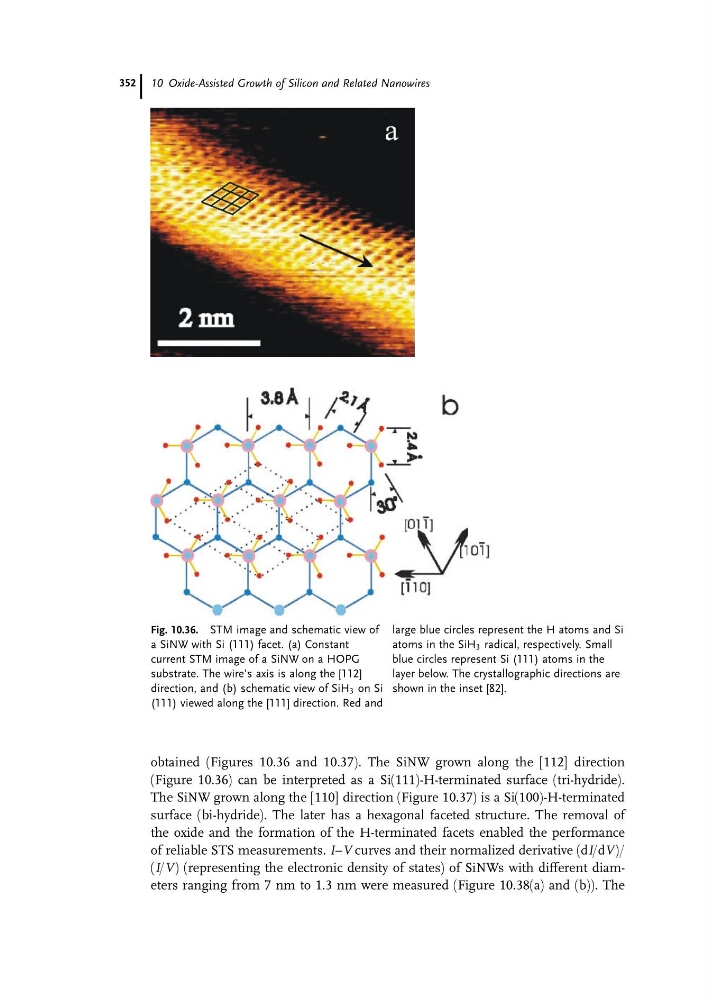
obtained (Figures 10.36 and 10.37). The SiNW grown along the [112] direction
(Figure 10.36) can be interpreted as a Si(111)-H-terminated surface (tri-hydride).
The SiNW grown along the [110] direction (Figure 10.37) is a Si(100)-H-terminated
surface (bi-hydride). The later has a hexagonal faceted structure. The removal of
the oxide and the formation of the H-terminated facets enabled the performance
of reliable STS measurements. I–V curves and their normalized derivative (dI/dV)/
(I/V) (representing the electronic density of states) of SiNWs with different diameters ranging from 7 nm to 1.3 nm were measured (Figure 10.38(a) and (b)). The
Fig. 10.36. STM image and schematic view of
a SiNW with Si (111) facet. (a) Constant
current STM image of a SiNW on a HOPG
substrate. The wire’s axis is along the [112]
direction, and (b) schematic view of SiH 3 on Si
(111) viewed along the [111] direction. Red and
large blue circles represent the H atoms and Si
atoms in the SiH 3 radical, respectively. Small
blue circles represent Si (111) atoms in the
layer below. The crystallographic directions are
shown in the inset [82].
10 Oxide-Assisted Growth of Silicon and Related Nanowires
352
(Figure 10.36) can be interpreted as a Si(111)-H-terminated surface (tri-hydride).
The SiNW grown along the [110] direction (Figure 10.37) is a Si(100)-H-terminated
surface (bi-hydride). The later has a hexagonal faceted structure. The removal of
the oxide and the formation of the H-terminated facets enabled the performance
of reliable STS measurements. I–V curves and their normalized derivative (dI/dV)/
(I/V) (representing the electronic density of states) of SiNWs with different diameters ranging from 7 nm to 1.3 nm were measured (Figure 10.38(a) and (b)). The
Fig. 10.36. STM image and schematic view of
a SiNW with Si (111) facet. (a) Constant
current STM image of a SiNW on a HOPG
substrate. The wire’s axis is along the [112]
direction, and (b) schematic view of SiH 3 on Si
(111) viewed along the [111] direction. Red and
large blue circles represent the H atoms and Si
atoms in the SiH 3 radical, respectively. Small
blue circles represent Si (111) atoms in the
layer below. The crystallographic directions are
shown in the inset [82].
10 Oxide-Assisted Growth of Silicon and Related Nanowires
352