

2.4 Modes in Circular Waveguides
65
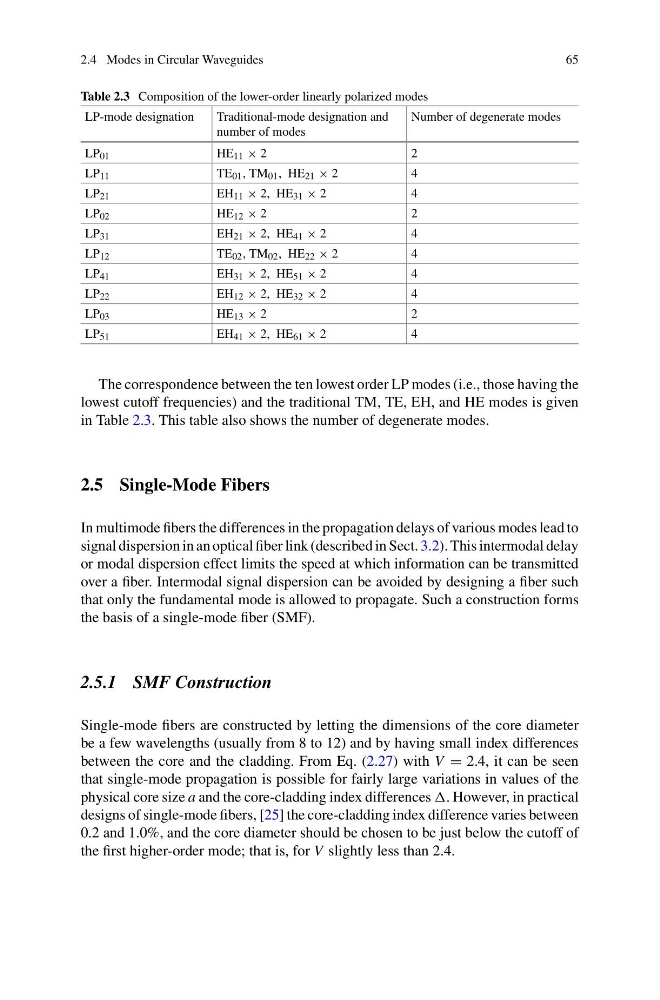
Table 2.3 Composition of the lower-order linearly polarized modes
LP-mode designation
Traditional-mode designation and
number of modes
Number of degenerate modes
LP 01
HE 11 × 2
2
LP 11
TE 01 , TM 01 , HE 21 × 2
4
LP 21
EH 11 × 2, HE 31 × 2
4
LP 02
HE 12 × 2
2
LP 31
EH 21 × 2, HE 41 × 2
4
LP 12
TE 02 , TM 02 , HE 22 × 2
4
LP 41
EH 31 × 2, HE 51 × 2
4
LP 22
EH 12 × 2, HE 32 × 2
4
LP 03
HE 13 × 2
2
LP 51
EH 41 × 2, HE 61 × 2
4
The correspondence between the ten lowest order LP modes (i.e., those having the
lowest cutoff frequencies) and the traditional TM, TE, EH, and HE modes is given
in Table 2.3. This table also shows the number of degenerate modes.
2.5 Single-Mode Fibers
In multimode fibers the differences in the propagation delays of various modes lead to
signal dispersion in an optical fiber link (described in Sect. 3.2). This intermodal delay
or modal dispersion effect limits the speed at which information can be transmitted
over a fiber. Intermodal signal dispersion can be avoided by designing a fiber such
that only the fundamental mode is allowed to propagate. Such a construction forms
the basis of a single-mode fiber (SMF).
2.5.1 SMF Construction
Single-mode fibers are constructed by letting the dimensions of the core diameter
be a few wavelengths (usually from 8 to 12) and by having small index differences
between the core and the cladding. From Eq. (2.27) with V = 2.4, it can be seen
that single-mode propagation is possible for fairly large variations in values of the
physical core size a and the core-cladding index differences . However, in practical
designs of single-mode fibers, [25] the core-cladding index difference varies between
0.2 and 1.0%, and the core diameter should be chosen to be just below the cutoff of
the first higher-order mode; that is, for V slightly less than 2.4.
65
Table 2.3 Composition of the lower-order linearly polarized modes
LP-mode designation
Traditional-mode designation and
number of modes
Number of degenerate modes
LP 01
HE 11 × 2
2
LP 11
TE 01 , TM 01 , HE 21 × 2
4
LP 21
EH 11 × 2, HE 31 × 2
4
LP 02
HE 12 × 2
2
LP 31
EH 21 × 2, HE 41 × 2
4
LP 12
TE 02 , TM 02 , HE 22 × 2
4
LP 41
EH 31 × 2, HE 51 × 2
4
LP 22
EH 12 × 2, HE 32 × 2
4
LP 03
HE 13 × 2
2
LP 51
EH 41 × 2, HE 61 × 2
4
The correspondence between the ten lowest order LP modes (i.e., those having the
lowest cutoff frequencies) and the traditional TM, TE, EH, and HE modes is given
in Table 2.3. This table also shows the number of degenerate modes.
2.5 Single-Mode Fibers
In multimode fibers the differences in the propagation delays of various modes lead to
signal dispersion in an optical fiber link (described in Sect. 3.2). This intermodal delay
or modal dispersion effect limits the speed at which information can be transmitted
over a fiber. Intermodal signal dispersion can be avoided by designing a fiber such
that only the fundamental mode is allowed to propagate. Such a construction forms
the basis of a single-mode fiber (SMF).
2.5.1 SMF Construction
Single-mode fibers are constructed by letting the dimensions of the core diameter
be a few wavelengths (usually from 8 to 12) and by having small index differences
between the core and the cladding. From Eq. (2.27) with V = 2.4, it can be seen
that single-mode propagation is possible for fairly large variations in values of the
physical core size a and the core-cladding index differences . However, in practical
designs of single-mode fibers, [25] the core-cladding index difference varies between
0.2 and 1.0%, and the core diameter should be chosen to be just below the cutoff of
the first higher-order mode; that is, for V slightly less than 2.4.