

64
2 Optical Fiber Structures and Light Guiding Principles
LP 01
LP 11
LP 21
LP 02
Cutoff
V = 2.405
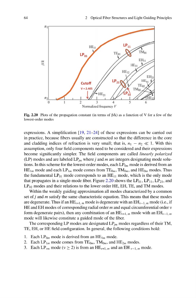
Fig. 2.20 Plots of the propagation constant (in terms of β/k) as a function of V for a few of the
lowest-order modes
expressions. A simplification [19, 21–24] of these expressions can be carried out
in practice, because fibers usually are constructed so that the difference in the core
and cladding indices of refraction is very small; that is, n 1 − n 2 1. With this
assumption, only four field components need to be considered and their expressions
become significantly simpler. The field components are called linearly polarized
(LP) modes and are labeled LP jm where j and m are integers designating mode solutions. In this scheme for the lowest-order modes, each LP 0m mode is derived from an
HE 1m mode and each LP 1m mode comes from TE 0m , TM 0m , and HE 0m modes. Thus
the fundamental LP 01 mode corresponds to an HE 11 mode, which is the only mode
that propagates in a single-mode fiber. Figure 2.20 shows the LP 01 , LP 11 , LP 21 , and
LP 02 modes and their relations to the lower order HE, EH, TE, and TM modes.
Within the weakly guiding approximation all modes characterized by a common
set of j and m satisfy the same characteristic equation. This means that these modes
are degenerate. Thus if an HE v+1, m mode is degenerate with an EH v−1, m mode (i.e., if
HE and EH modes of corresponding radial order m and equal circumferential order ν
form degenerate pairs), then any combination of an HE v+1, m mode with an EH v−1, m
mode will likewise constitute a guided mode of the fiber.
The corresponding LP modes are designated LP jm modes regardless of their TM,
TE, EH, or HE field configuration. In general, the following conditions hold:
1. Each LP 0m mode is derived from an HE 1m mode.
2. Each LP 1m mode comes from TE 0m , TM 0m , and HE 2m modes.
3. Each LP vm mode (ν ≥ 2) is from an HE v+1, m and an EH v−1, m mode.
2 Optical Fiber Structures and Light Guiding Principles
LP 01
LP 11
LP 21
LP 02
Cutoff
V = 2.405
Fig. 2.20 Plots of the propagation constant (in terms of β/k) as a function of V for a few of the
lowest-order modes
expressions. A simplification [19, 21–24] of these expressions can be carried out
in practice, because fibers usually are constructed so that the difference in the core
and cladding indices of refraction is very small; that is, n 1 − n 2 1. With this
assumption, only four field components need to be considered and their expressions
become significantly simpler. The field components are called linearly polarized
(LP) modes and are labeled LP jm where j and m are integers designating mode solutions. In this scheme for the lowest-order modes, each LP 0m mode is derived from an
HE 1m mode and each LP 1m mode comes from TE 0m , TM 0m , and HE 0m modes. Thus
the fundamental LP 01 mode corresponds to an HE 11 mode, which is the only mode
that propagates in a single-mode fiber. Figure 2.20 shows the LP 01 , LP 11 , LP 21 , and
LP 02 modes and their relations to the lower order HE, EH, TE, and TM modes.
Within the weakly guiding approximation all modes characterized by a common
set of j and m satisfy the same characteristic equation. This means that these modes
are degenerate. Thus if an HE v+1, m mode is degenerate with an EH v−1, m mode (i.e., if
HE and EH modes of corresponding radial order m and equal circumferential order ν
form degenerate pairs), then any combination of an HE v+1, m mode with an EH v−1, m
mode will likewise constitute a guided mode of the fiber.
The corresponding LP modes are designated LP jm modes regardless of their TM,
TE, EH, or HE field configuration. In general, the following conditions hold:
1. Each LP 0m mode is derived from an HE 1m mode.
2. Each LP 1m mode comes from TE 0m , TM 0m , and HE 2m modes.
3. Each LP vm mode (ν ≥ 2) is from an HE v+1, m and an EH v−1, m mode.