

602
14 Basic Measurement and Monitoring Techniques
where n 1 is the core refractive index of the fiber. The number “2” in the denominator
accounts for the fact that light travels a length L from the source to the break point
and then another length L on the return trip back to the source.
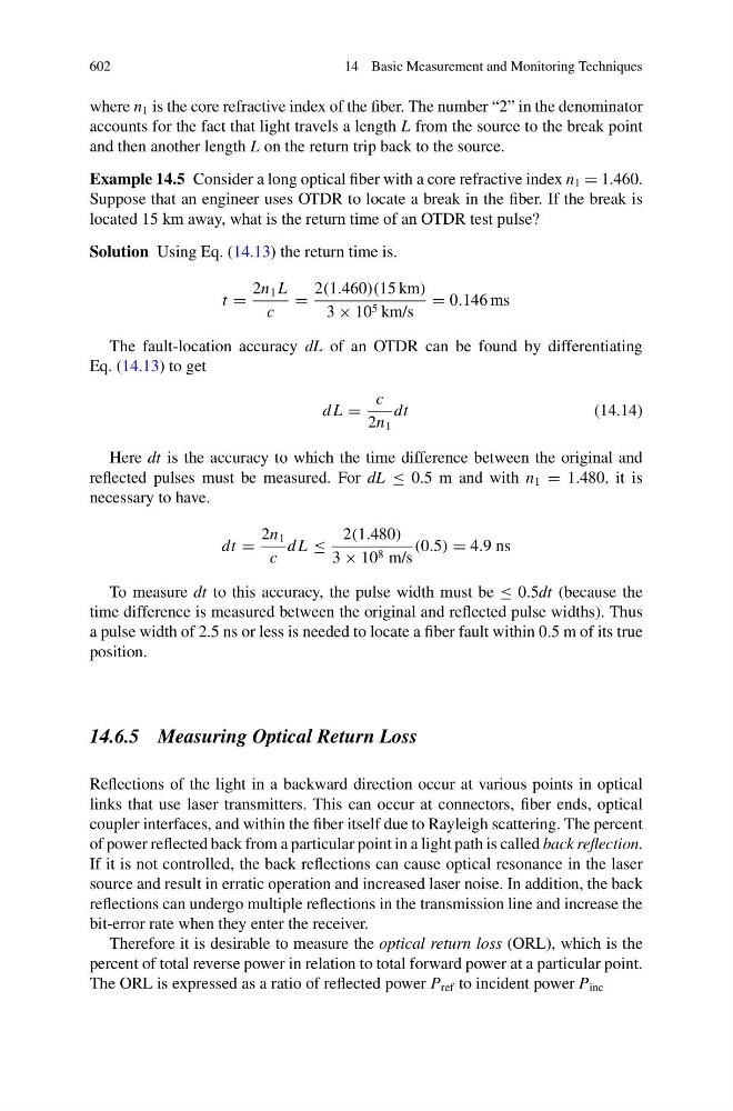
Example 14.5 Consider a long optical fiber with a core refractive index n 1 = 1.460.
Suppose that an engineer uses OTDR to locate a break in the fiber. If the break is
located 15 km away, what is the return time of an OTDR test pulse?
Solution Using Eq. (14.13) the return time is.
t =
2n 1 L
c
=
2(1.460)(15 km)
3 × 10 5 km/s
= 0.146 ms
The fault-location accuracy dL of an OTDR can be found by differentiating
Eq. (14.13) to get
d L =
c
2n 1
dt
(14.14)
Here dt is the accuracy to which the time difference between the original and
reflected pulses must be measured. For dL ≤ 0.5 m and with n 1 = 1.480, it is
necessary to have.
dt =
2n 1
c
d L ≤
2(1.480)
3 × 10 8 m/s
(0.5) = 4.9 ns
To measure dt to this accuracy, the pulse width must be ≤ 0.5dt (because the
time difference is measured between the original and reflected pulse widths). Thus
a pulse width of 2.5 ns or less is needed to locate a fiber fault within 0.5 m of its true
position.
14.6.5 Measuring Optical Return Loss
Reflections of the light in a backward direction occur at various points in optical
links that use laser transmitters. This can occur at connectors, fiber ends, optical
coupler interfaces, and within the fiber itself due to Rayleigh scattering. The percent
of power reflected back from a particular point in a light path is called back reflection.
If it is not controlled, the back reflections can cause optical resonance in the laser
source and result in erratic operation and increased laser noise. In addition, the back
reflections can undergo multiple reflections in the transmission line and increase the
bit-error rate when they enter the receiver.
Therefore it is desirable to measure the optical return loss (ORL), which is the
percent of total reverse power in relation to total forward power at a particular point.
The ORL is expressed as a ratio of reflected power P ref to incident power P inc