

14.6 Optical Time-Domain Reflectometer
601
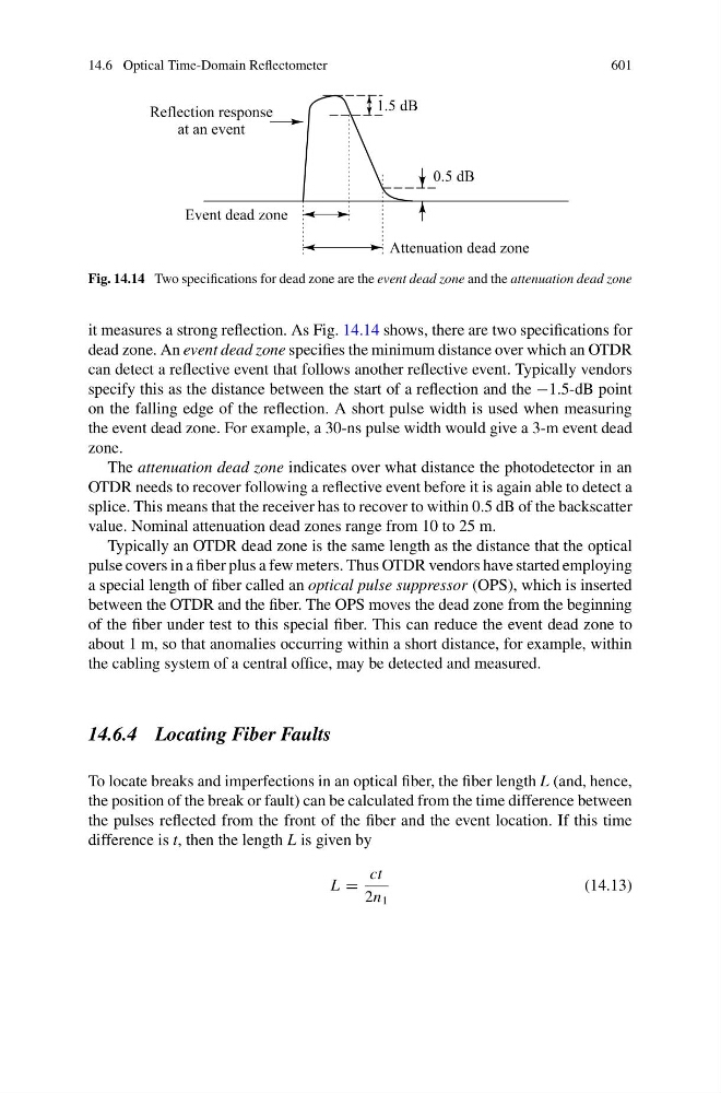
Fig. 14.14 Two specifications for dead zone are the event dead zone and the attenuation dead zone
it measures a strong reflection. As Fig. 14.14 shows, there are two specifications for
dead zone. An event dead zone specifies the minimum distance over which an OTDR
can detect a reflective event that follows another reflective event. Typically vendors
specify this as the distance between the start of a reflection and the −1.5-dB point
on the falling edge of the reflection. A short pulse width is used when measuring
the event dead zone. For example, a 30-ns pulse width would give a 3-m event dead
zone.
The attenuation dead zone indicates over what distance the photodetector in an
OTDR needs to recover following a reflective event before it is again able to detect a
splice. This means that the receiver has to recover to within 0.5 dB of the backscatter
value. Nominal attenuation dead zones range from 10 to 25 m.
Typically an OTDR dead zone is the same length as the distance that the optical
pulse covers in a fiber plus a few meters. Thus OTDR vendors have started employing
a special length of fiber called an optical pulse suppressor (OPS), which is inserted
between the OTDR and the fiber. The OPS moves the dead zone from the beginning
of the fiber under test to this special fiber. This can reduce the event dead zone to
about 1 m, so that anomalies occurring within a short distance, for example, within
the cabling system of a central office, may be detected and measured.
14.6.4 Locating Fiber Faults
To locate breaks and imperfections in an optical fiber, the fiber length L (and, hence,
the position of the break or fault) can be calculated from the time difference between
the pulses reflected from the front of the fiber and the event location. If this time
difference is t, then the length L is given by
L =
ct
2n 1
(14.13)