

598
14 Basic Measurement and Monitoring Techniques
and the measurement point in the fiber. In addition to the trace, an OTDR can place
a number next to an event on the display and give a list of these numbers and their
corresponding measurement information in a table below the trace.
The backscattered waveform has four distinct features:
• A large initial pulse resulting from Fresnel reflection at the input end of the fiber
• A long decaying tail resulting from Rayleigh scattering in the reverse direction
as the input pulse travels along the fiber
• Abrupt shifts in the curve caused by optical loss at joints or connectors in the fiber
line
• Positive spikes arising from Fresnel reflection at the far end of the fiber, at fiber
joints, and at fiber imperfections.
Fresnel reflection and Rayleigh scattering principally produce the backscattered
light. Fresnel reflection occurs when light enters a medium having a different index of
refraction. For a glass–air interface, when light of power P 0 is incident perpendicular
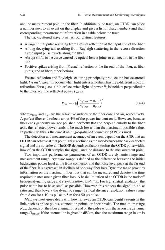
to the interface, the reflected power P ref is
P re f = P 0
n f iber − n air
n f iber + n air
2
(14.4)
where n fiber and n air are the refractive indices of the fiber core and air, respectively.
A perfect fiber end reflects about 4% of the power incident on it. However, because
fiber ends generally are not polished perfectly flat and perpendicularly to the fiber
axis, the reflected power tends to be much lower than the maximum possible value.
In particular, this is the case if an angle-polished connector (APC) is used.
The detection and measurement accuracy of an event depend on the SNR that an
OTDR can achieve at that point. This is defined as the ratio between the back-reflected
signal and the noise level. The SNR depends on factors such as the OTDR pulse width,
how often the OTDR samples the signal, and the distance to the measurement point.
Two important performance parameters of an OTDR are dynamic range and
measurement range. Dynamic range is defined as the difference between the initial
backscatter power level at the front connector and the noise level peak at the far end
of the fiber. It is expressed in decibels of one-way fiber loss. Dynamic range provides
information on the maximum fiber loss that can be measured and denotes the time
required to measure a given fiber loss. A basic limitation of an OTDR is the tradeoff
between dynamic range and event location resolution. For high spatial resolution, the
pulse width has to be as small as possible. However, this reduces the signal-to-noise
ratio and thus lowers the dynamic range. Typical distance resolution values range
from 8 cm for a 10-ns pulse to 5 m for a 50 μs pulse.
Measurement range deals with how far away an OTDR can identify events in the
link, such as splice points, connection points, or fiber breaks. The maximum range
R max depends on the fiber attenuation α and on the pulse width, that is, on the dynamic
range D OTDR . If the attenuation is given in dB/km, then the maximum range in km is