

526
13 Fiber Optic Communication Networks
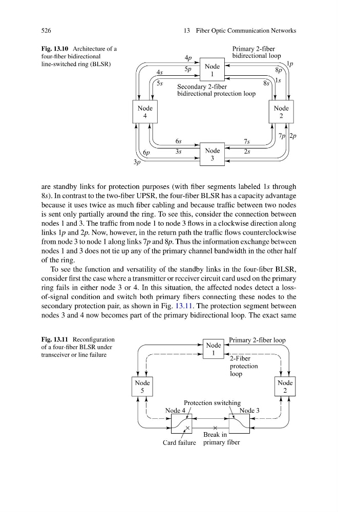
Fig. 13.10 Architecture of a
four-fiber bidirectional
line-switched ring (BLSR)
are standby links for protection purposes (with fiber segments labeled 1s through
8s). In contrast to the two-fiber UPSR, the four-fiber BLSR has a capacity advantage
because it uses twice as much fiber cabling and because traffic between two nodes
is sent only partially around the ring. To see this, consider the connection between
nodes 1 and 3. The traffic from node 1 to node 3 flows in a clockwise direction along
links 1p and 2p. Now, however, in the return path the traffic flows counterclockwise
from node 3 to node 1 along links 7p and 8p. Thus the information exchange between
nodes 1 and 3 does not tie up any of the primary channel bandwidth in the other half
of the ring.
To see the function and versatility of the standby links in the four-fiber BLSR,
consider first the case where a transmitter or receiver circuit card used on the primary
ring fails in either node 3 or 4. In this situation, the affected nodes detect a lossof-signal condition and switch both primary fibers connecting these nodes to the
secondary protection pair, as shown in Fig. 13.11. The protection segment between
nodes 3 and 4 now becomes part of the primary bidirectional loop. The exact same
Fig. 13.11 Reconfiguration
of a four-fiber BLSR under
transceiver or line failure
13 Fiber Optic Communication Networks
Fig. 13.10 Architecture of a
four-fiber bidirectional
line-switched ring (BLSR)
are standby links for protection purposes (with fiber segments labeled 1s through
8s). In contrast to the two-fiber UPSR, the four-fiber BLSR has a capacity advantage
because it uses twice as much fiber cabling and because traffic between two nodes
is sent only partially around the ring. To see this, consider the connection between
nodes 1 and 3. The traffic from node 1 to node 3 flows in a clockwise direction along
links 1p and 2p. Now, however, in the return path the traffic flows counterclockwise
from node 3 to node 1 along links 7p and 8p. Thus the information exchange between
nodes 1 and 3 does not tie up any of the primary channel bandwidth in the other half
of the ring.
To see the function and versatility of the standby links in the four-fiber BLSR,
consider first the case where a transmitter or receiver circuit card used on the primary
ring fails in either node 3 or 4. In this situation, the affected nodes detect a lossof-signal condition and switch both primary fibers connecting these nodes to the
secondary protection pair, as shown in Fig. 13.11. The protection segment between
nodes 3 and 4 now becomes part of the primary bidirectional loop. The exact same
Fig. 13.11 Reconfiguration
of a four-fiber BLSR under
transceiver or line failure