

13.3 Basic SONET/SDH Concepts
527
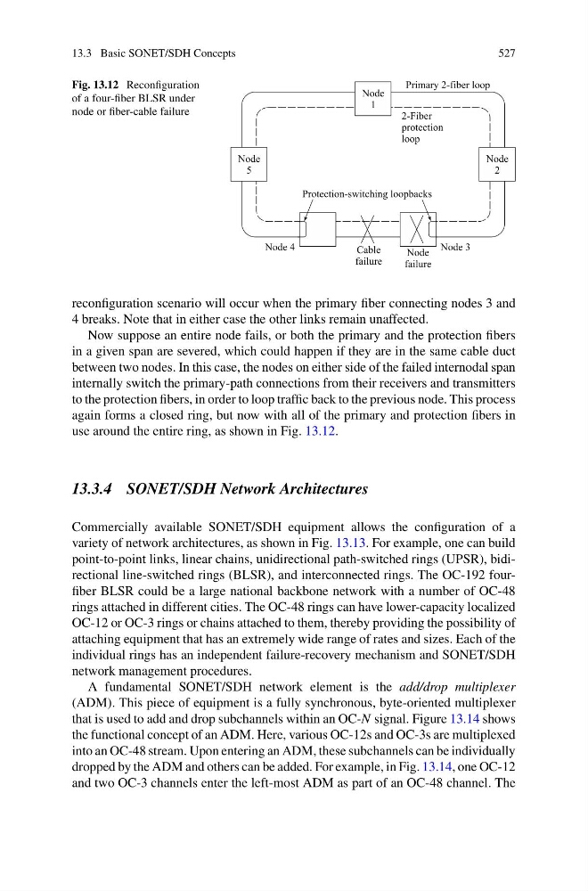
Fig. 13.12 Reconfiguration
of a four-fiber BLSR under
node or fiber-cable failure
reconfiguration scenario will occur when the primary fiber connecting nodes 3 and
4 breaks. Note that in either case the other links remain unaffected.
Now suppose an entire node fails, or both the primary and the protection fibers
in a given span are severed, which could happen if they are in the same cable duct
between two nodes. In this case, the nodes on either side of the failed internodal span
internally switch the primary-path connections from their receivers and transmitters
to the protection fibers, in order to loop traffic back to the previous node. This process
again forms a closed ring, but now with all of the primary and protection fibers in
use around the entire ring, as shown in Fig. 13.12.
13.3.4 SONET/SDH Network Architectures
Commercially available SONET/SDH equipment allows the configuration of a
variety of network architectures, as shown in Fig. 13.13. For example, one can build
point-to-point links, linear chains, unidirectional path-switched rings (UPSR), bidirectional line-switched rings (BLSR), and interconnected rings. The OC-192 fourfiber BLSR could be a large national backbone network with a number of OC-48
rings attached in different cities. The OC-48 rings can have lower-capacity localized
OC-12 or OC-3 rings or chains attached to them, thereby providing the possibility of
attaching equipment that has an extremely wide range of rates and sizes. Each of the
individual rings has an independent failure-recovery mechanism and SONET/SDH
network management procedures.
A fundamental SONET/SDH network element is the add/drop multiplexer
(ADM). This piece of equipment is a fully synchronous, byte-oriented multiplexer
that is used to add and drop subchannels within an OC-N signal. Figure 13.14 shows
the functional concept of an ADM. Here, various OC-12s and OC-3s are multiplexed
into an OC-48 stream. Upon entering an ADM, these subchannels can be individually
dropped by the ADM and others can be added. For example, in Fig. 13.14, one OC-12
and two OC-3 channels enter the left-most ADM as part of an OC-48 channel. The
527
Fig. 13.12 Reconfiguration
of a four-fiber BLSR under
node or fiber-cable failure
reconfiguration scenario will occur when the primary fiber connecting nodes 3 and
4 breaks. Note that in either case the other links remain unaffected.
Now suppose an entire node fails, or both the primary and the protection fibers
in a given span are severed, which could happen if they are in the same cable duct
between two nodes. In this case, the nodes on either side of the failed internodal span
internally switch the primary-path connections from their receivers and transmitters
to the protection fibers, in order to loop traffic back to the previous node. This process
again forms a closed ring, but now with all of the primary and protection fibers in
use around the entire ring, as shown in Fig. 13.12.
13.3.4 SONET/SDH Network Architectures
Commercially available SONET/SDH equipment allows the configuration of a
variety of network architectures, as shown in Fig. 13.13. For example, one can build
point-to-point links, linear chains, unidirectional path-switched rings (UPSR), bidirectional line-switched rings (BLSR), and interconnected rings. The OC-192 fourfiber BLSR could be a large national backbone network with a number of OC-48
rings attached in different cities. The OC-48 rings can have lower-capacity localized
OC-12 or OC-3 rings or chains attached to them, thereby providing the possibility of
attaching equipment that has an extremely wide range of rates and sizes. Each of the
individual rings has an independent failure-recovery mechanism and SONET/SDH
network management procedures.
A fundamental SONET/SDH network element is the add/drop multiplexer
(ADM). This piece of equipment is a fully synchronous, byte-oriented multiplexer
that is used to add and drop subchannels within an OC-N signal. Figure 13.14 shows
the functional concept of an ADM. Here, various OC-12s and OC-3s are multiplexed
into an OC-48 stream. Upon entering an ADM, these subchannels can be individually
dropped by the ADM and others can be added. For example, in Fig. 13.14, one OC-12
and two OC-3 channels enter the left-most ADM as part of an OC-48 channel. The