

13.3 Basic SONET/SDH Concepts
525
The common abbreviations of these configurations are given in parentheses. They
are also referred to as unidirectional or bidirectional self-healing rings (USHRs or
BSHRs), respectively.
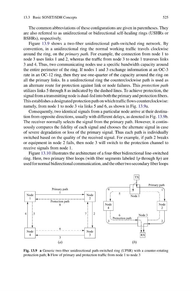
Figure 13.9 shows a two-fiber unidirectional path-switched ring network. By
convention, in a unidirectional ring the normal working traffic travels clockwise
around the ring, on the primary path. For example, the connection from node 1 to
node 3 uses links 1 and 2, whereas the traffic from node 3 to node 1 traverses links
3 and 4. Thus, two communicating nodes use a specific bandwidth capacity around
the entire perimeter of the ring. If nodes 1 and 3 exchange information at an OC-3
rate in an OC-12 ring, then they use one-quarter of the capacity around the ring on
all the primary links. In a unidirectional ring the counterclockwise path is used as
an alternate route for protection against link or node failures. This protection path
utilizes links 5 through 8 as indicated by the dashed lines. To achieve protection, the
signal from a transmitting node is dual-fed into both the primary and protection fibers.
This establishes a designated protection path on which traffic flows counterclockwise:
namely, from node 1 to node 3 via links 5 and 6, as shown in Fig. 13.9a.
Consequently, two identical signals from a particular node arrive at their destination from opposite directions, usually with different delays, as denoted in Fig. 13.9b.
The receiver normally selects the signal from the primary path. However, it continuously compares the fidelity of each signal and chooses the alternate signal in case
of severe degradation or loss of the primary signal. Thus each path is individually
switched based on the quality of the received signal. For example, if path 2 breaks
or equipment in node 2 fails, then node 3 will switch to the protection channel to
receive signals from node 1.
Figure 13.10 illustrates the architecture of a four-fiber bidirectional line-switched
ring. Here, two primary fiber loops (with fiber segments labeled 1p through 8p) are
used for normal bidirectional communication, and the other two secondary fiber loops
Fig. 13.9 a Generic two-fiber unidirectional path-switched ring (UPSR) with a counter-rotating
protection path; b Flow of primary and protection traffic from node 1 to node 3
525
The common abbreviations of these configurations are given in parentheses. They
are also referred to as unidirectional or bidirectional self-healing rings (USHRs or
BSHRs), respectively.
Figure 13.9 shows a two-fiber unidirectional path-switched ring network. By
convention, in a unidirectional ring the normal working traffic travels clockwise
around the ring, on the primary path. For example, the connection from node 1 to
node 3 uses links 1 and 2, whereas the traffic from node 3 to node 1 traverses links
3 and 4. Thus, two communicating nodes use a specific bandwidth capacity around
the entire perimeter of the ring. If nodes 1 and 3 exchange information at an OC-3
rate in an OC-12 ring, then they use one-quarter of the capacity around the ring on
all the primary links. In a unidirectional ring the counterclockwise path is used as
an alternate route for protection against link or node failures. This protection path
utilizes links 5 through 8 as indicated by the dashed lines. To achieve protection, the
signal from a transmitting node is dual-fed into both the primary and protection fibers.
This establishes a designated protection path on which traffic flows counterclockwise:
namely, from node 1 to node 3 via links 5 and 6, as shown in Fig. 13.9a.
Consequently, two identical signals from a particular node arrive at their destination from opposite directions, usually with different delays, as denoted in Fig. 13.9b.
The receiver normally selects the signal from the primary path. However, it continuously compares the fidelity of each signal and chooses the alternate signal in case
of severe degradation or loss of the primary signal. Thus each path is individually
switched based on the quality of the received signal. For example, if path 2 breaks
or equipment in node 2 fails, then node 3 will switch to the protection channel to
receive signals from node 1.
Figure 13.10 illustrates the architecture of a four-fiber bidirectional line-switched
ring. Here, two primary fiber loops (with fiber segments labeled 1p through 8p) are
used for normal bidirectional communication, and the other two secondary fiber loops
Fig. 13.9 a Generic two-fiber unidirectional path-switched ring (UPSR) with a counter-rotating
protection path; b Flow of primary and protection traffic from node 1 to node 3