

466
11 Basics of Optical Amplifiers
power from the pumps travels upstream (from the receiver toward the sender), the SRS
effect progressively transfers power from shorter pump wavelengths to longer signal
wavelengths. This occurs over the characteristic Raman gain length L G = g R P/A eff ,
where P is the pump laser power and A eff is the effective area of the transmission fiber,
which is approximately equal to the actual fiber cross-sectional area (see Chap. 12 for
a detailed definition). In general, noise factors limit the practical gain of a distributed
Raman amplifier to less than 20 dB.
11.7.2 Pump Lasers for Raman Amplifiers
Pump lasers with high output powers in the 1400-to-1500-nm region are required
for Raman amplification of C-band and L-band signals. Lasers that provide fiber
launch powers of up to 300 mW are available in standard 14-pin butterfly packages.
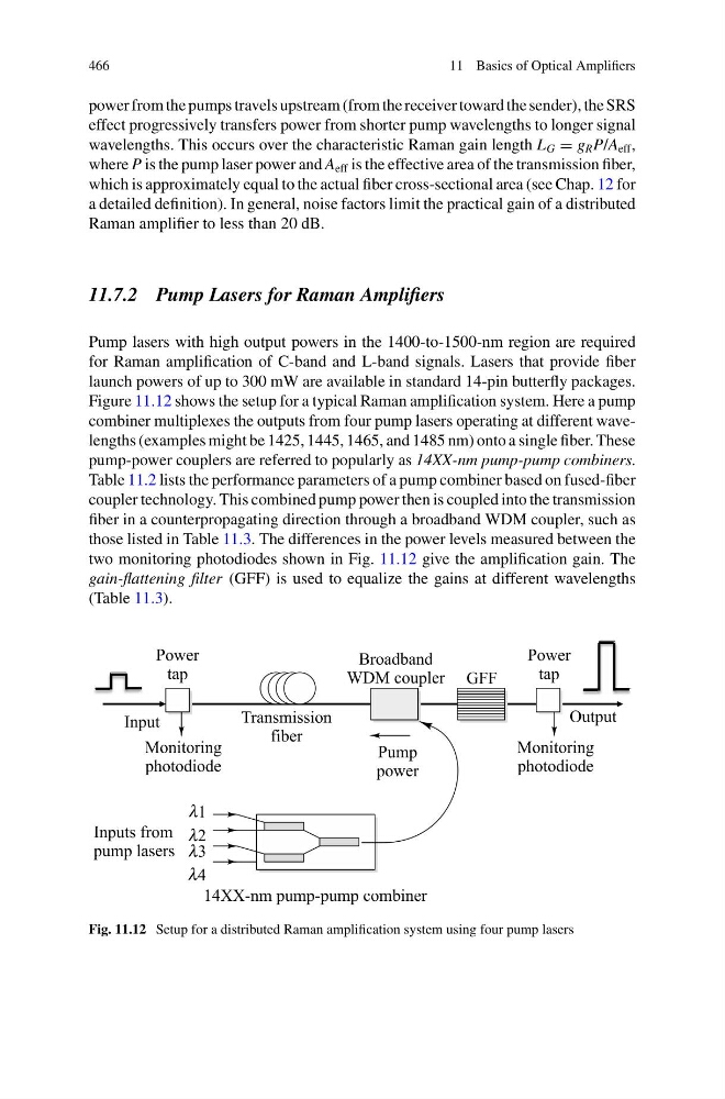
Figure 11.12 shows the setup for a typical Raman amplification system. Here a pump
combiner multiplexes the outputs from four pump lasers operating at different wavelengths (examples might be 1425, 1445, 1465, and 1485 nm) onto a single fiber. These
pump-power couplers are referred to popularly as 14XX-nm pump-pump combiners.
Table 11.2 lists the performance parameters of a pump combiner based on fused-fiber
coupler technology. This combined pump power then is coupled into the transmission
fiber in a counterpropagating direction through a broadband WDM coupler, such as
those listed in Table 11.3. The differences in the power levels measured between the
two monitoring photodiodes shown in Fig. 11.12 give the amplification gain. The
gain-flattening filter (GFF) is used to equalize the gains at different wavelengths
(Table 11.3).
Fig. 11.12 Setup for a distributed Raman amplification system using four pump lasers
11 Basics of Optical Amplifiers
power from the pumps travels upstream (from the receiver toward the sender), the SRS
effect progressively transfers power from shorter pump wavelengths to longer signal
wavelengths. This occurs over the characteristic Raman gain length L G = g R P/A eff ,
where P is the pump laser power and A eff is the effective area of the transmission fiber,
which is approximately equal to the actual fiber cross-sectional area (see Chap. 12 for
a detailed definition). In general, noise factors limit the practical gain of a distributed
Raman amplifier to less than 20 dB.
11.7.2 Pump Lasers for Raman Amplifiers
Pump lasers with high output powers in the 1400-to-1500-nm region are required
for Raman amplification of C-band and L-band signals. Lasers that provide fiber
launch powers of up to 300 mW are available in standard 14-pin butterfly packages.
Figure 11.12 shows the setup for a typical Raman amplification system. Here a pump
combiner multiplexes the outputs from four pump lasers operating at different wavelengths (examples might be 1425, 1445, 1465, and 1485 nm) onto a single fiber. These
pump-power couplers are referred to popularly as 14XX-nm pump-pump combiners.
Table 11.2 lists the performance parameters of a pump combiner based on fused-fiber
coupler technology. This combined pump power then is coupled into the transmission
fiber in a counterpropagating direction through a broadband WDM coupler, such as
those listed in Table 11.3. The differences in the power levels measured between the
two monitoring photodiodes shown in Fig. 11.12 give the amplification gain. The
gain-flattening filter (GFF) is used to equalize the gains at different wavelengths
(Table 11.3).
Fig. 11.12 Setup for a distributed Raman amplification system using four pump lasers