

11.7 Raman Optical Amplifiers
465
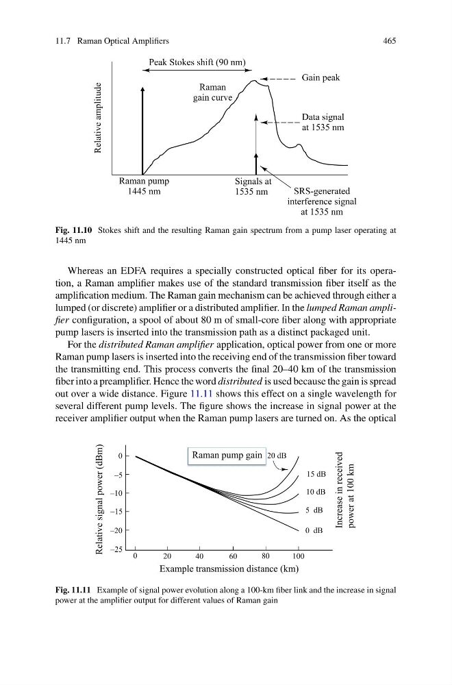
Fig. 11.10 Stokes shift and the resulting Raman gain spectrum from a pump laser operating at
1445 nm
Whereas an EDFA requires a specially constructed optical fiber for its operation, a Raman amplifier makes use of the standard transmission fiber itself as the
amplification medium. The Raman gain mechanism can be achieved through either a
lumped (or discrete) amplifier or a distributed amplifier. In the lumped Raman amplifier configuration, a spool of about 80 m of small-core fiber along with appropriate
pump lasers is inserted into the transmission path as a distinct packaged unit.
For the distributed Raman amplifier application, optical power from one or more
Raman pump lasers is inserted into the receiving end of the transmission fiber toward
the transmitting end. This process converts the final 20–40 km of the transmission
fiber into a preamplifier. Hence the word distributed is used because the gain is spread
out over a wide distance. Figure 11.11 shows this effect on a single wavelength for
several different pump levels. The figure shows the increase in signal power at the
receiver amplifier output when the Raman pump lasers are turned on. As the optical
Example transmission distance (km)
Relative signal power (dBm)
Increase in received
power at 100 km
Raman pump gain
Fig. 11.11 Example of signal power evolution along a 100-km fiber link and the increase in signal
power at the amplifier output for different values of Raman gain
465
Fig. 11.10 Stokes shift and the resulting Raman gain spectrum from a pump laser operating at
1445 nm
Whereas an EDFA requires a specially constructed optical fiber for its operation, a Raman amplifier makes use of the standard transmission fiber itself as the
amplification medium. The Raman gain mechanism can be achieved through either a
lumped (or discrete) amplifier or a distributed amplifier. In the lumped Raman amplifier configuration, a spool of about 80 m of small-core fiber along with appropriate
pump lasers is inserted into the transmission path as a distinct packaged unit.
For the distributed Raman amplifier application, optical power from one or more
Raman pump lasers is inserted into the receiving end of the transmission fiber toward
the transmitting end. This process converts the final 20–40 km of the transmission
fiber into a preamplifier. Hence the word distributed is used because the gain is spread
out over a wide distance. Figure 11.11 shows this effect on a single wavelength for
several different pump levels. The figure shows the increase in signal power at the
receiver amplifier output when the Raman pump lasers are turned on. As the optical
Example transmission distance (km)
Relative signal power (dBm)
Increase in received
power at 100 km
Raman pump gain
Fig. 11.11 Example of signal power evolution along a 100-km fiber link and the increase in signal
power at the amplifier output for different values of Raman gain