

456
11 Basics of Optical Amplifiers
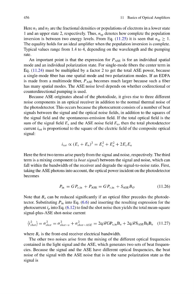
Here n 1 and n 2 are the fractional densities or populations of electrons in a lower state
1 and an upper state 2, respectively. Thus, n sp denotes how complete the population
inversion is between two energy levels. From Eq. (11.25) it is seen that n sp ≥ 1.
The equality holds for an ideal amplifier when the population inversion is complete.
Typical values range from 1.4 to 4, depending on the wavelength and the pumping
rate.
An important point is that the expression for P ASE is for an individual spatial
mode and an individual polarization state. For single-mode fibers the center term in
Eq. (11.24) must be multiplied by a factor 2 to get the total ASE power, because
a single-mode fiber has one spatial mode and two polarization modes. If an EDFA
is made from a multimode fiber, P ASE becomes much larger because such a fiber
has many spatial modes. The ASE noise level depends on whether codirectional or
counterdirectional pumping is used.
Because ASE originates ahead of the photodiode, it gives rise to three different
noise components in an optical receiver in addition to the normal thermal noise of
the photodetector. This occurs because the photocurrent consists of a number of beat
signals between the signal and the optical noise fields, in addition to the squares of
the signal field and the spontaneous-emission field. If the total optical field is the
sum of the signal field E s and the ASE noise field E n , then the total photodetector
current i tot is proportional to the square of the electric field of the composite optical
signal:
i tot ∝ (E s + E n )
2
= E
2
s + E
2
n + 2E s E n
Here the first two terms arise purely from the signal and noise, respectively. The third
term is a mixing component (a beat signal) between the signal and noise, which can
fall within the bandwidth of the receiver and degrade the signal-to-noise ratio. First,
taking the ASE photons into account, the optical power incident on the photodetector
becomes
P in = G P s,in + P ASE = G P s,in + S ASE B O
(11.26)
Note that B o can be reduced significantly if an optical filter precedes the photodetector. Substituting P in into Eq. (6.6) and inserting the resulting expression for the
photocurrent i p into Eq. (6.12) to find the shot noise then yields the total mean-square
signal-plus-ASE shot-noise current
i
2
shot
= σ
2
shot = σ
2
shot−s + σ
2
shot−AS E = 2qRGP s,in B e + 2qRS ASE B 0 B e (11.27)
where B e is the front-end receiver electrical bandwidth.
The other two noises arise from the mixing of the different optical frequencies
contained in the light signal and the ASE, which generates two sets of beat frequencies. Because the signal and the ASE have different optical frequencies, the beat
noise of the signal with the ASE noise that is in the same polarization state as the
signal is
11 Basics of Optical Amplifiers
Here n 1 and n 2 are the fractional densities or populations of electrons in a lower state
1 and an upper state 2, respectively. Thus, n sp denotes how complete the population
inversion is between two energy levels. From Eq. (11.25) it is seen that n sp ≥ 1.
The equality holds for an ideal amplifier when the population inversion is complete.
Typical values range from 1.4 to 4, depending on the wavelength and the pumping
rate.
An important point is that the expression for P ASE is for an individual spatial
mode and an individual polarization state. For single-mode fibers the center term in
Eq. (11.24) must be multiplied by a factor 2 to get the total ASE power, because
a single-mode fiber has one spatial mode and two polarization modes. If an EDFA
is made from a multimode fiber, P ASE becomes much larger because such a fiber
has many spatial modes. The ASE noise level depends on whether codirectional or
counterdirectional pumping is used.
Because ASE originates ahead of the photodiode, it gives rise to three different
noise components in an optical receiver in addition to the normal thermal noise of
the photodetector. This occurs because the photocurrent consists of a number of beat
signals between the signal and the optical noise fields, in addition to the squares of
the signal field and the spontaneous-emission field. If the total optical field is the
sum of the signal field E s and the ASE noise field E n , then the total photodetector
current i tot is proportional to the square of the electric field of the composite optical
signal:
i tot ∝ (E s + E n )
2
= E
2
s + E
2
n + 2E s E n
Here the first two terms arise purely from the signal and noise, respectively. The third
term is a mixing component (a beat signal) between the signal and noise, which can
fall within the bandwidth of the receiver and degrade the signal-to-noise ratio. First,
taking the ASE photons into account, the optical power incident on the photodetector
becomes
P in = G P s,in + P ASE = G P s,in + S ASE B O
(11.26)
Note that B o can be reduced significantly if an optical filter precedes the photodetector. Substituting P in into Eq. (6.6) and inserting the resulting expression for the
photocurrent i p into Eq. (6.12) to find the shot noise then yields the total mean-square
signal-plus-ASE shot-noise current
i
2
shot
= σ
2
shot = σ
2
shot−s + σ
2
shot−AS E = 2qRGP s,in B e + 2qRS ASE B 0 B e (11.27)
where B e is the front-end receiver electrical bandwidth.
The other two noises arise from the mixing of the different optical frequencies
contained in the light signal and the ASE, which generates two sets of beat frequencies. Because the signal and the ASE have different optical frequencies, the beat
noise of the signal with the ASE noise that is in the same polarization state as the
signal is