

10.8 Summary
433
10.12 Consider a wavelength multiplexer made from circulators and fiber Bragg
gratings as shown in Fig. 10.22. Assume the input optical power of each wavelength λ 1 through λ 4 is 1 mW. Let both the insertion loss and the throughput
loss of each FBG be 0.25 dB, and let the insertion loss of a circulator be
0.6 dB. What is the power level of each wavelength λ 1 through λ 4 emerging
from the final circulator C 4 ?
10.13 A 0.5-cm-long fiber Bragg grating is constructed by irradiating a single-mode
fiber with a pair of 244-nm ultraviolet light beams. The fiber has V = 2.405
and n eff = 1.48. The half- angle between the two beams is θ/2 = 13.5°. If the
photo-induced index change is 2.5 × 10
−4 , find the following:
(a) The grating period,
(b) The Bragg wavelength,
(c) The coupling coefficient,
(d) The full bandwidth λ measured between the zeros on either side of
R max ,
(e) The maximum reflectivity.
10.14 Consider a wavelength multiplexer made from a series of thin-film filters as
shown in Fig. 10.27. Assume the input optical power of each wavelength λ 1
through λ 4 is 1 mW. For each TFF let the throughput loss equal 1.0 dB and
let the reflection loss be 0.4 dB. What is the power level of each wavelength
λ 1 through λ 4 emerging from the final thin-film filter TFF 4 ?
Answers to Selected Problems.
10.1 Channel spacing is 4 nm; 5 channels can be utilized
10.2 λ 1 − λ 2 = 1550.00 − 1549.20 nm = 0.80 nm;
λ 31 − λ 32 = 1526.34 − 1525.56 nm = 0.78 nm
10.3 (a) 2%; (b) IL 0→1 = 0.36 dB, IL 0→2 = 17.0 (c) 0.27 dB
10.4 (a) P 1 = 107.4 μW, P 2 = 67.8 μW; (b) 0.58 dB; (c) P 1 /P 0 = 61%, P 2 /P 0 =
39
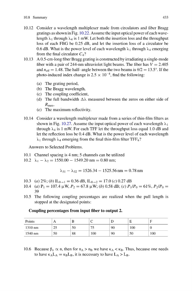
10.5 The following coupling percentages are realized when the pull length is
stopped at the designated points:
Coupling percentages from input fiber to output 2.
Points
A
B
C
D
E
F
1310 nm
25
50
75
90
100
0
1540 nm
50
88
100
90
50
100
10.6 Because β z ∝ n, then for n A > n B we have κ A < κ B . Thus, because one needs
to have κ A L A = κ B L B , it is necessary to have L A > L B .
433
10.12 Consider a wavelength multiplexer made from circulators and fiber Bragg
gratings as shown in Fig. 10.22. Assume the input optical power of each wavelength λ 1 through λ 4 is 1 mW. Let both the insertion loss and the throughput
loss of each FBG be 0.25 dB, and let the insertion loss of a circulator be
0.6 dB. What is the power level of each wavelength λ 1 through λ 4 emerging
from the final circulator C 4 ?
10.13 A 0.5-cm-long fiber Bragg grating is constructed by irradiating a single-mode
fiber with a pair of 244-nm ultraviolet light beams. The fiber has V = 2.405
and n eff = 1.48. The half- angle between the two beams is θ/2 = 13.5°. If the
photo-induced index change is 2.5 × 10
−4 , find the following:
(a) The grating period,
(b) The Bragg wavelength,
(c) The coupling coefficient,
(d) The full bandwidth λ measured between the zeros on either side of
R max ,
(e) The maximum reflectivity.
10.14 Consider a wavelength multiplexer made from a series of thin-film filters as
shown in Fig. 10.27. Assume the input optical power of each wavelength λ 1
through λ 4 is 1 mW. For each TFF let the throughput loss equal 1.0 dB and
let the reflection loss be 0.4 dB. What is the power level of each wavelength
λ 1 through λ 4 emerging from the final thin-film filter TFF 4 ?
Answers to Selected Problems.
10.1 Channel spacing is 4 nm; 5 channels can be utilized
10.2 λ 1 − λ 2 = 1550.00 − 1549.20 nm = 0.80 nm;
λ 31 − λ 32 = 1526.34 − 1525.56 nm = 0.78 nm
10.3 (a) 2%; (b) IL 0→1 = 0.36 dB, IL 0→2 = 17.0 (c) 0.27 dB
10.4 (a) P 1 = 107.4 μW, P 2 = 67.8 μW; (b) 0.58 dB; (c) P 1 /P 0 = 61%, P 2 /P 0 =
39
10.5 The following coupling percentages are realized when the pull length is
stopped at the designated points:
Coupling percentages from input fiber to output 2.
Points
A
B
C
D
E
F
1310 nm
25
50
75
90
100
0
1540 nm
50
88
100
90
50
100
10.6 Because β z ∝ n, then for n A > n B we have κ A < κ B . Thus, because one needs
to have κ A L A = κ B L B , it is necessary to have L A > L B .