

10.5 Dielectric Thin-Film Filter (TFF)
423
Table 10.7 Typical performance parameters for 8-channel DWDM and CWDM multiplexers based
on thin-film-filter technology
Parameter
50-GHz DWDM 100-GHz DWDM 20-nm CWDM
Center wavelength accuracy
±0.1 nm
±0.1 nm
±0.3 nm
Channel passband @ 0.5-dB bandwidth ±0.20 nm
±0.11 nm
±6.5 nm
Insertion loss (dB)
≤1.0
≤1.0
≤2.0
Ripple in passband (dB)
≤0.5
≤0.5
≤0.5
Adjacent channel isolation (dB)
≥23
≥20
≥15
Directivity (dB)
≥50
≥55
≥50
Optical return loss (dB)
≥40
≥50
≥45
Polarization dependent loss (dB)
≤0.1
≤ 0.1
≤0.1
Thermal wavelength drift (nm/°C)
<0.001
<0.001
<0.003
Optical power capability (mW)
500
500
500
two signals then are reflected from filter TFF 3 where they are joined by wavelength
λ 3 , which has passed through TFF 3 . After a similar process at filter TFF 4 , the four
wavelengths can be coupled into a fiber by means of a lens mechanism.
To separate the four wavelengths from one fiber into four physically independent
channels, the directions of the arrows in Fig. 10.27 are reversed. Because a light
beam loses some of its power at each TFF because the filters are not perfect, this
multiplexing architecture works for only a limited number of channels. This usually
is specified as being 16 channels or less.
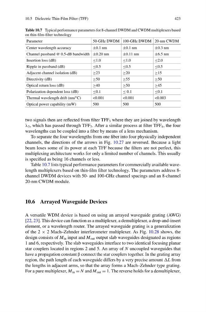
Table 10.7 lists typical performance parameters for commercially available wavelength multiplexers based on thin-film filter technology. The parameters address 8channel DWDM devices with 50- and 100-GHz channel spacings and an 8-channel
20-nm CWDM module.
10.6 Arrayed Waveguide Devices
A versatile WDM device is based on using an arrayed waveguide grating (AWG)
[22, 23]. This device can function as a multiplexer, a demultiplexer, a drop-and-insert
element, or a wavelength router. The arrayed waveguide grating is a generalization
of the 2 × 2 Mach–Zehnder interferometer multiplexer. As Fig. 10.28 shows, the
design consists of M in input and M out output slab waveguides designated as regions
1 and 6, respectively. The slab waveguides interface to two identical focusing planar
star couplers located in regions 2 and 5. An array of N uncoupled waveguides that
have a propagation constant β connect the star couplers together. In the grating array
region, the path length of each waveguide differs by a very precise amount L from
the lengths in adjacent arms, so that the array forms a Mach–Zehnder type grating.
For a pure multiplexer, M in = N and M out = 1. The reverse holds for a demultiplexer,
423
Table 10.7 Typical performance parameters for 8-channel DWDM and CWDM multiplexers based
on thin-film-filter technology
Parameter
50-GHz DWDM 100-GHz DWDM 20-nm CWDM
Center wavelength accuracy
±0.1 nm
±0.1 nm
±0.3 nm
Channel passband @ 0.5-dB bandwidth ±0.20 nm
±0.11 nm
±6.5 nm
Insertion loss (dB)
≤1.0
≤1.0
≤2.0
Ripple in passband (dB)
≤0.5
≤0.5
≤0.5
Adjacent channel isolation (dB)
≥23
≥20
≥15
Directivity (dB)
≥50
≥55
≥50
Optical return loss (dB)
≥40
≥50
≥45
Polarization dependent loss (dB)
≤0.1
≤ 0.1
≤0.1
Thermal wavelength drift (nm/°C)
<0.001
<0.001
<0.003
Optical power capability (mW)
500
500
500
two signals then are reflected from filter TFF 3 where they are joined by wavelength
λ 3 , which has passed through TFF 3 . After a similar process at filter TFF 4 , the four
wavelengths can be coupled into a fiber by means of a lens mechanism.
To separate the four wavelengths from one fiber into four physically independent
channels, the directions of the arrows in Fig. 10.27 are reversed. Because a light
beam loses some of its power at each TFF because the filters are not perfect, this
multiplexing architecture works for only a limited number of channels. This usually
is specified as being 16 channels or less.
Table 10.7 lists typical performance parameters for commercially available wavelength multiplexers based on thin-film filter technology. The parameters address 8channel DWDM devices with 50- and 100-GHz channel spacings and an 8-channel
20-nm CWDM module.
10.6 Arrayed Waveguide Devices
A versatile WDM device is based on using an arrayed waveguide grating (AWG)
[22, 23]. This device can function as a multiplexer, a demultiplexer, a drop-and-insert
element, or a wavelength router. The arrayed waveguide grating is a generalization
of the 2 × 2 Mach–Zehnder interferometer multiplexer. As Fig. 10.28 shows, the
design consists of M in input and M out output slab waveguides designated as regions
1 and 6, respectively. The slab waveguides interface to two identical focusing planar
star couplers located in regions 2 and 5. An array of N uncoupled waveguides that
have a propagation constant β connect the star couplers together. In the grating array
region, the path length of each waveguide differs by a very precise amount L from
the lengths in adjacent arms, so that the array forms a Mach–Zehnder type grating.
For a pure multiplexer, M in = N and M out = 1. The reverse holds for a demultiplexer,