

424
10 Wavelength Division Multiplexing (WDM)
λ 1
λ 2
λ 3
λ 4
λ 1 , λ 2 , λ 3 , λ 4
1
2
3
4
5
6
At (4): ΔΦ = 2π n eff ΔL / λ c
n eff = effective index
λ c = center wavelength
Lens
region
Grating array waveguides
Input slab
waveguide
array
Output slab
waveguide
array
region
Lens
At (6): Δλ FSR = λ c
2 / (ΔL n eff )
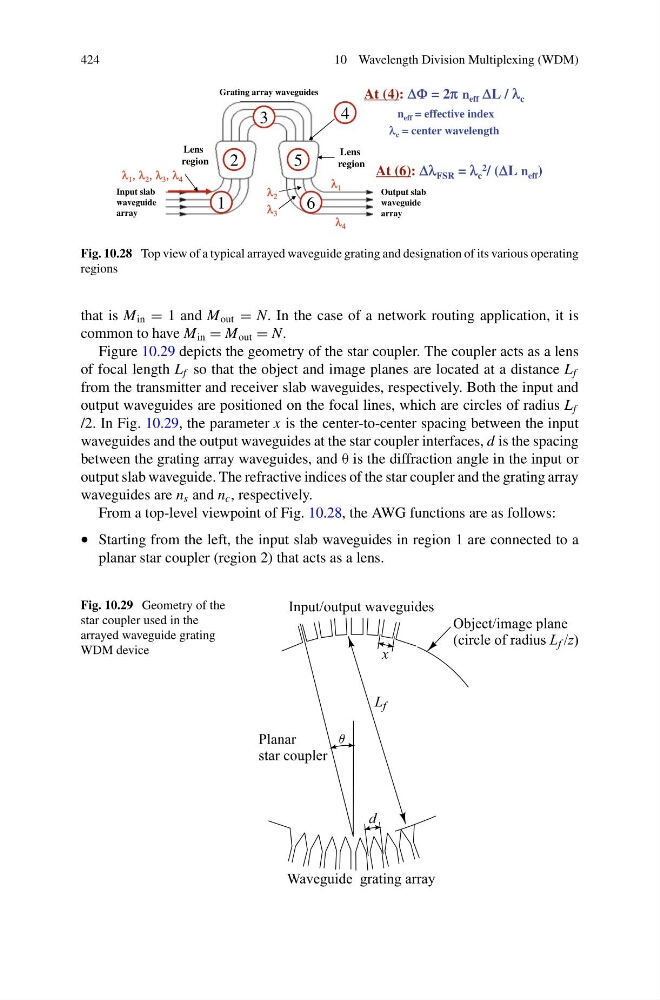
Fig. 10.28 Top view of a typical arrayed waveguide grating and designation of its various operating
regions
that is M in = 1 and M out = N. In the case of a network routing application, it is
common to have M in = M out = N.
Figure 10.29 depicts the geometry of the star coupler. The coupler acts as a lens
of focal length L f so that the object and image planes are located at a distance L f
from the transmitter and receiver slab waveguides, respectively. Both the input and
output waveguides are positioned on the focal lines, which are circles of radius L f
/2. In Fig. 10.29, the parameter x is the center-to-center spacing between the input
waveguides and the output waveguides at the star coupler interfaces, d is the spacing
between the grating array waveguides, and θ is the diffraction angle in the input or
output slab waveguide. The refractive indices of the star coupler and the grating array
waveguides are n s and n c , respectively.
From a top-level viewpoint of Fig. 10.28, the AWG functions are as follows:
• Starting from the left, the input slab waveguides in region 1 are connected to a
planar star coupler (region 2) that acts as a lens.
Fig. 10.29 Geometry of the
star coupler used in the
arrayed waveguide grating
WDM device
10 Wavelength Division Multiplexing (WDM)
λ 1
λ 2
λ 3
λ 4
λ 1 , λ 2 , λ 3 , λ 4
1
2
3
4
5
6
At (4): ΔΦ = 2π n eff ΔL / λ c
n eff = effective index
λ c = center wavelength
Lens
region
Grating array waveguides
Input slab
waveguide
array
Output slab
waveguide
array
region
Lens
At (6): Δλ FSR = λ c
2 / (ΔL n eff )
Fig. 10.28 Top view of a typical arrayed waveguide grating and designation of its various operating
regions
that is M in = 1 and M out = N. In the case of a network routing application, it is
common to have M in = M out = N.
Figure 10.29 depicts the geometry of the star coupler. The coupler acts as a lens
of focal length L f so that the object and image planes are located at a distance L f
from the transmitter and receiver slab waveguides, respectively. Both the input and
output waveguides are positioned on the focal lines, which are circles of radius L f
/2. In Fig. 10.29, the parameter x is the center-to-center spacing between the input
waveguides and the output waveguides at the star coupler interfaces, d is the spacing
between the grating array waveguides, and θ is the diffraction angle in the input or
output slab waveguide. The refractive indices of the star coupler and the grating array
waveguides are n s and n c , respectively.
From a top-level viewpoint of Fig. 10.28, the AWG functions are as follows:
• Starting from the left, the input slab waveguides in region 1 are connected to a
planar star coupler (region 2) that acts as a lens.
Fig. 10.29 Geometry of the
star coupler used in the
arrayed waveguide grating
WDM device