

422
10 Wavelength Division Multiplexing (WDM)
Table 10.6 Typical
parameter values of
commercial available 50-GHz
thin-film filters
Parameter
Unit
Value
Channel passband
GHz
>±10 at 0.5 dB
Insertion loss at f c ±10 GHz
dB
<3.5
Polarization-dependent loss
dB
<0.20
Isolation (adjacent channels)
dB
>25
Isolation (nonadjacent channels) dB
>40
Optical return loss
dB
>45
Polarization-mode dispersion
ps
<0.2
Chromatic dispersion
ps/nm <50
filter is made such that if the input spectrum contains wavelengths λ 1 through λ N ,
then only λ k passes through the device. All the other wavelengths are reflected.
Thin-film filters are available in a wide range of passbands varying from 50 to
800 GHz and higher for widely spaced channels. Table 10.6 lists some operational
characteristics of commercially available 50-GHz multilayer dielectric thin-film
filters for use in fiber optic communication systems.
10.5.2 TFF Applications to WDM Links
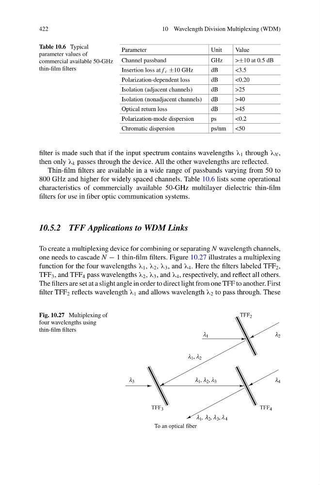
To create a multiplexing device for combining or separating N wavelength channels,
one needs to cascade N − 1 thin-film filters. Figure 10.27 illustrates a multiplexing
function for the four wavelengths λ 1 , λ 2 , λ 3 , and λ 4 . Here the filters labeled TFF 2 ,
TFF 3 , and TFF 4 pass wavelengths λ 2 , λ 3 , and λ 4 , respectively, and reflect all others.
The filters are set at a slight angle in order to direct light from one TFF to another. First
filter TFF 2 reflects wavelength λ 1 and allows wavelength λ 2 to pass through. These
Fig. 10.27 Multiplexing of
four wavelengths using
thin-film filters
10 Wavelength Division Multiplexing (WDM)
Table 10.6 Typical
parameter values of
commercial available 50-GHz
thin-film filters
Parameter
Unit
Value
Channel passband
GHz
>±10 at 0.5 dB
Insertion loss at f c ±10 GHz
dB
<3.5
Polarization-dependent loss
dB
<0.20
Isolation (adjacent channels)
dB
>25
Isolation (nonadjacent channels) dB
>40
Optical return loss
dB
>45
Polarization-mode dispersion
ps
<0.2
Chromatic dispersion
ps/nm <50
filter is made such that if the input spectrum contains wavelengths λ 1 through λ N ,
then only λ k passes through the device. All the other wavelengths are reflected.
Thin-film filters are available in a wide range of passbands varying from 50 to
800 GHz and higher for widely spaced channels. Table 10.6 lists some operational
characteristics of commercially available 50-GHz multilayer dielectric thin-film
filters for use in fiber optic communication systems.
10.5.2 TFF Applications to WDM Links
To create a multiplexing device for combining or separating N wavelength channels,
one needs to cascade N − 1 thin-film filters. Figure 10.27 illustrates a multiplexing
function for the four wavelengths λ 1 , λ 2 , λ 3 , and λ 4 . Here the filters labeled TFF 2 ,
TFF 3 , and TFF 4 pass wavelengths λ 2 , λ 3 , and λ 4 , respectively, and reflect all others.
The filters are set at a slight angle in order to direct light from one TFF to another. First
filter TFF 2 reflects wavelength λ 1 and allows wavelength λ 2 to pass through. These
Fig. 10.27 Multiplexing of
four wavelengths using
thin-film filters