

10.5 Dielectric Thin-Film Filter (TFF)
421
sharper transmission peaks with lower minimum transmission coefficients. That is,
the higher the finesse the narrower the passband and the sharper the boundaries.
Drill Problem 10.6 Suppose the end mirrors in an etalon have the same reflectivities R 1 = R 2 = R. Show that for devices with R = 0.5, 0.7, and 0.9, the
corresponding values of the finesse are 4.4, 8.8, and 29.8. This shows that the
finesse value is larger for sharper peaked Airy functions, that is, very high
finesse values require highly reflective mirrors.
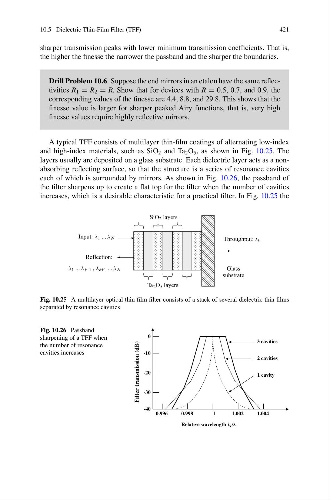
A typical TFF consists of multilayer thin-film coatings of alternating low-index
and high-index materials, such as SiO 2 and Ta 2 O 5 , as shown in Fig. 10.25. The
layers usually are deposited on a glass substrate. Each dielectric layer acts as a nonabsorbing reflecting surface, so that the structure is a series of resonance cavities
each of which is surrounded by mirrors. As shown in Fig. 10.26, the passband of
the filter sharpens up to create a flat top for the filter when the number of cavities
increases, which is a desirable characteristic for a practical filter. In Fig. 10.25 the
Fig. 10.25 A multilayer optical thin film filter consists of a stack of several dielectric thin films
separated by resonance cavities
Fig. 10.26 Passband
sharpening of a TFF when
the number of resonance
cavities increases
1 cavity
2 cavities
3 cavities
Filter transmission (dB)
Relative wavelength λ c /λ
0.998
1
1.004
1.002
0
-10
-20
-40
-30
0.996
421
sharper transmission peaks with lower minimum transmission coefficients. That is,
the higher the finesse the narrower the passband and the sharper the boundaries.
Drill Problem 10.6 Suppose the end mirrors in an etalon have the same reflectivities R 1 = R 2 = R. Show that for devices with R = 0.5, 0.7, and 0.9, the
corresponding values of the finesse are 4.4, 8.8, and 29.8. This shows that the
finesse value is larger for sharper peaked Airy functions, that is, very high
finesse values require highly reflective mirrors.
A typical TFF consists of multilayer thin-film coatings of alternating low-index
and high-index materials, such as SiO 2 and Ta 2 O 5 , as shown in Fig. 10.25. The
layers usually are deposited on a glass substrate. Each dielectric layer acts as a nonabsorbing reflecting surface, so that the structure is a series of resonance cavities
each of which is surrounded by mirrors. As shown in Fig. 10.26, the passband of
the filter sharpens up to create a flat top for the filter when the number of cavities
increases, which is a desirable characteristic for a practical filter. In Fig. 10.25 the
Fig. 10.25 A multilayer optical thin film filter consists of a stack of several dielectric thin films
separated by resonance cavities
Fig. 10.26 Passband
sharpening of a TFF when
the number of resonance
cavities increases
1 cavity
2 cavities
3 cavities
Filter transmission (dB)
Relative wavelength λ c /λ
0.998
1
1.004
1.002
0
-10
-20
-40
-30
0.996