

402
10 Wavelength Division Multiplexing (WDM)
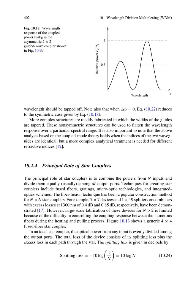
Fig. 10.12 Wavelength
response of the coupled
power P 2 /P 0 in the
asymmetric 2 × 2
guided-wave coupler shown
in Fig. 10.9b
wavelength should be tapped off. Note also that when = 0, Eq. (10.22) reduces
to the symmetric case given by Eq. (10.18).
More complex structures are readily fabricated in which the widths of the guides
are tapered. These nonsymmetric structures can be used to flatten the wavelength
response over a particular spectral range. It is also important to note that the above
analysis based on the coupled-mode theory holds when the indices of the two waveguides are identical, but a more complex analytical treatment is needed for different
refractive indices [12].
10.2.4 Principal Role of Star Couplers
The principal role of star couplers is to combine the powers from N inputs and
divide them equally (usually) among M output ports. Techniques for creating star
couplers include fused fibers, gratings, micro-optic technologies, and integratedoptics schemes. The fiber-fusion technique has been a popular construction method
for N × N star couplers. For example, 7 × 7 devices and 1 × 19 splitters or combiners
with excess losses at 1300 nm of 0.4 dB and 0.85 dB, respectively, have been demonstrated [17]. However, large-scale fabrication of these devices for N > 2 is limited
because of the difficulty in controlling the coupling response between the numerous
fibers during the heating and pulling process. Figure 10.13 shows a generic 4 × 4
fused-fiber star coupler.
In an ideal star coupler, the optical power from any input is evenly divided among
the output ports. The total loss of the device consists of its splitting loss plus the
excess loss in each path through the star. The splitting loss is given in decibels by
Splitting loss = −10 log
1
N
= 10 log N
(10.24)
10 Wavelength Division Multiplexing (WDM)
Fig. 10.12 Wavelength
response of the coupled
power P 2 /P 0 in the
asymmetric 2 × 2
guided-wave coupler shown
in Fig. 10.9b
wavelength should be tapped off. Note also that when = 0, Eq. (10.22) reduces
to the symmetric case given by Eq. (10.18).
More complex structures are readily fabricated in which the widths of the guides
are tapered. These nonsymmetric structures can be used to flatten the wavelength
response over a particular spectral range. It is also important to note that the above
analysis based on the coupled-mode theory holds when the indices of the two waveguides are identical, but a more complex analytical treatment is needed for different
refractive indices [12].
10.2.4 Principal Role of Star Couplers
The principal role of star couplers is to combine the powers from N inputs and
divide them equally (usually) among M output ports. Techniques for creating star
couplers include fused fibers, gratings, micro-optic technologies, and integratedoptics schemes. The fiber-fusion technique has been a popular construction method
for N × N star couplers. For example, 7 × 7 devices and 1 × 19 splitters or combiners
with excess losses at 1300 nm of 0.4 dB and 0.85 dB, respectively, have been demonstrated [17]. However, large-scale fabrication of these devices for N > 2 is limited
because of the difficulty in controlling the coupling response between the numerous
fibers during the heating and pulling process. Figure 10.13 shows a generic 4 × 4
fused-fiber star coupler.
In an ideal star coupler, the optical power from any input is evenly divided among
the output ports. The total loss of the device consists of its splitting loss plus the
excess loss in each path through the star. The splitting loss is given in decibels by
Splitting loss = −10 log
1
N
= 10 log N
(10.24)