

10.2 Passive Optical Couplers
401
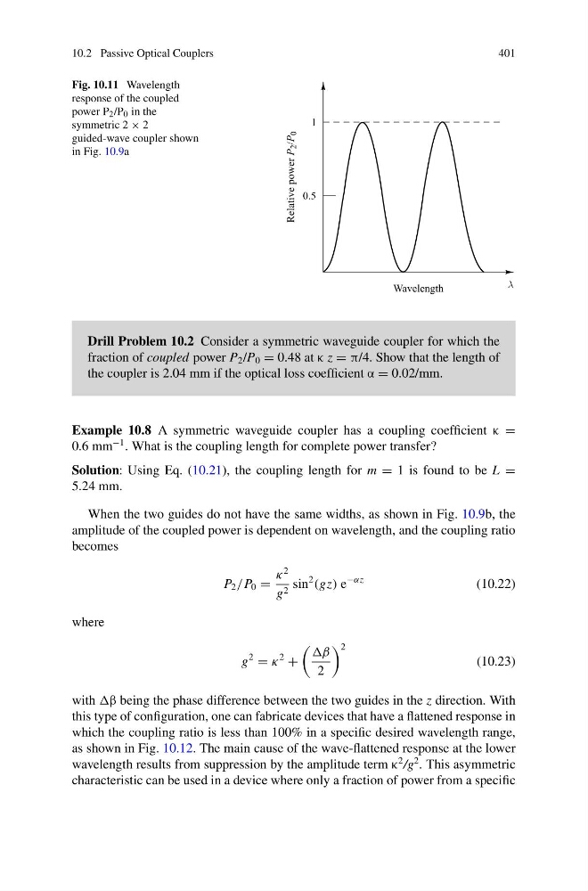
Fig. 10.11 Wavelength
response of the coupled
power P 2 /P 0 in the
symmetric 2 × 2
guided-wave coupler shown
in Fig. 10.9a
Drill Problem 10.2 Consider a symmetric waveguide coupler for which the
fraction of coupled power P 2 /P 0 = 0.48 at κ z = π/4. Show that the length of
the coupler is 2.04 mm if the optical loss coefficient α = 0.02/mm.
Example 10.8 A symmetric waveguide coupler has a coupling coefficient κ =
0.6 mm
−1 . What is the coupling length for complete power transfer?
Solution: Using Eq. (10.21), the coupling length for m = 1 is found to be L =
5.24 mm.
When the two guides do not have the same widths, as shown in Fig. 10.9b, the
amplitude of the coupled power is dependent on wavelength, and the coupling ratio
becomes
P 2 /P 0 =
κ
2
g 2 sin
2
(gz) e
−αz
(10.22)
where
g
2
= κ
2
+
2
2
(10.23)
with being the phase difference between the two guides in the z direction. With
this type of configuration, one can fabricate devices that have a flattened response in
which the coupling ratio is less than 100% in a specific desired wavelength range,
as shown in Fig. 10.12. The main cause of the wave-flattened response at the lower
wavelength results from suppression by the amplitude term κ
2 /g
2 . This asymmetric
characteristic can be used in a device where only a fraction of power from a specific
401
Fig. 10.11 Wavelength
response of the coupled
power P 2 /P 0 in the
symmetric 2 × 2
guided-wave coupler shown
in Fig. 10.9a
Drill Problem 10.2 Consider a symmetric waveguide coupler for which the
fraction of coupled power P 2 /P 0 = 0.48 at κ z = π/4. Show that the length of
the coupler is 2.04 mm if the optical loss coefficient α = 0.02/mm.
Example 10.8 A symmetric waveguide coupler has a coupling coefficient κ =
0.6 mm
−1 . What is the coupling length for complete power transfer?
Solution: Using Eq. (10.21), the coupling length for m = 1 is found to be L =
5.24 mm.
When the two guides do not have the same widths, as shown in Fig. 10.9b, the
amplitude of the coupled power is dependent on wavelength, and the coupling ratio
becomes
P 2 /P 0 =
κ
2
g 2 sin
2
(gz) e
−αz
(10.22)
where
g
2
= κ
2
+
2
2
(10.23)
with being the phase difference between the two guides in the z direction. With
this type of configuration, one can fabricate devices that have a flattened response in
which the coupling ratio is less than 100% in a specific desired wavelength range,
as shown in Fig. 10.12. The main cause of the wave-flattened response at the lower
wavelength results from suppression by the amplitude term κ
2 /g
2 . This asymmetric
characteristic can be used in a device where only a fraction of power from a specific