

400
10 Wavelength Division Multiplexing (WDM)
where the coupling coefficient is
κ =
2β
2
y qe
−qs
β z w
q 2 + β 2
y
(10.19)
This is a function of the waveguide propagation constants β y and β z (in the y and z
directions, respectively), the gap width d and separation s, and the extinction coefficient q in the y direction (i.e., the exponential falloff in the y direction) outside the
waveguide, which is
q
2
= β
2
z − k
2
1
(10.20)
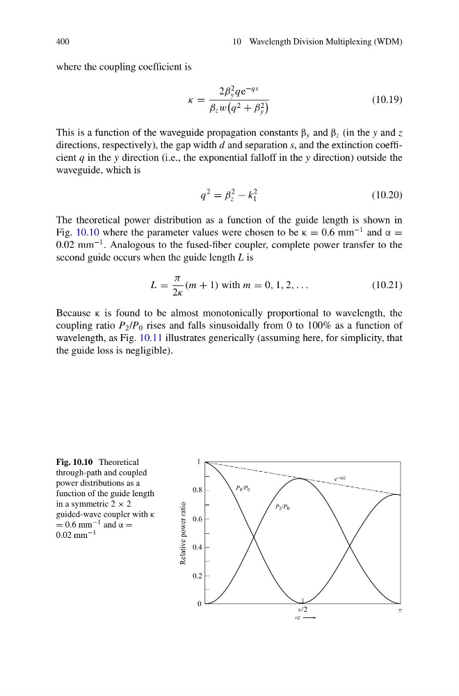
The theoretical power distribution as a function of the guide length is shown in
Fig. 10.10 where the parameter values were chosen to be κ = 0.6 mm
−1 and α =
0.02 mm
−1 . Analogous to the fused-fiber coupler, complete power transfer to the
second guide occurs when the guide length L is
L =
π
2κ
(m + 1) with m = 0, 1, 2, . . .
(10.21)
Because κ is found to be almost monotonically proportional to wavelength, the
coupling ratio P 2 /P 0 rises and falls sinusoidally from 0 to 100% as a function of
wavelength, as Fig. 10.11 illustrates generically (assuming here, for simplicity, that
the guide loss is negligible).
Fig. 10.10 Theoretical
through-path and coupled
power distributions as a
function of the guide length
in a symmetric 2 × 2
guided-wave coupler with κ
= 0.6 mm −1 and α =
0.02 mm −1
10 Wavelength Division Multiplexing (WDM)
where the coupling coefficient is
κ =
2β
2
y qe
−qs
β z w
q 2 + β 2
y
(10.19)
This is a function of the waveguide propagation constants β y and β z (in the y and z
directions, respectively), the gap width d and separation s, and the extinction coefficient q in the y direction (i.e., the exponential falloff in the y direction) outside the
waveguide, which is
q
2
= β
2
z − k
2
1
(10.20)
The theoretical power distribution as a function of the guide length is shown in
Fig. 10.10 where the parameter values were chosen to be κ = 0.6 mm
−1 and α =
0.02 mm
−1 . Analogous to the fused-fiber coupler, complete power transfer to the
second guide occurs when the guide length L is
L =
π
2κ
(m + 1) with m = 0, 1, 2, . . .
(10.21)
Because κ is found to be almost monotonically proportional to wavelength, the
coupling ratio P 2 /P 0 rises and falls sinusoidally from 0 to 100% as a function of
wavelength, as Fig. 10.11 illustrates generically (assuming here, for simplicity, that
the guide loss is negligible).
Fig. 10.10 Theoretical
through-path and coupled
power distributions as a
function of the guide length
in a symmetric 2 × 2
guided-wave coupler with κ
= 0.6 mm −1 and α =
0.02 mm −1