

10.2 Passive Optical Couplers
399
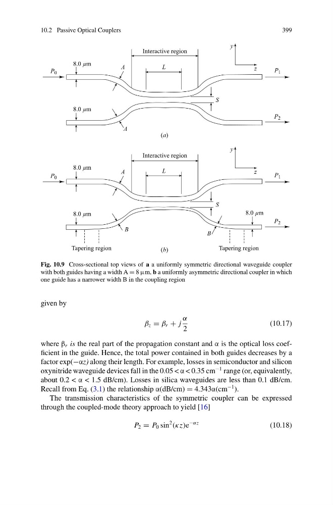
Fig. 10.9 Cross-sectional top views of a a uniformly symmetric directional waveguide coupler
with both guides having a width A = 8 μm, b a uniformly asymmetric directional coupler in which
one guide has a narrower width B in the coupling region
given by
β z = β r + j
α
2
(10.17)
where β r is the real part of the propagation constant and α is the optical loss coefficient in the guide. Hence, the total power contained in both guides decreases by a
factor exp(−αz) along their length. For example, losses in semiconductor and silicon
oxynitride waveguide devices fall in the 0.05 < α < 0.35 cm
−1 range (or, equivalently,
about 0.2 < α < 1.5 dB/cm). Losses in silica waveguides are less than 0.1 dB/cm.
Recall from Eq. (3.1) the relationship α(dB/cm) = 4.343α(cm
−1 ).
The transmission characteristics of the symmetric coupler can be expressed
through the coupled-mode theory approach to yield [16]
P 2 = P 0 sin
2
(κz)e
−αz
(10.18)
399
Fig. 10.9 Cross-sectional top views of a a uniformly symmetric directional waveguide coupler
with both guides having a width A = 8 μm, b a uniformly asymmetric directional coupler in which
one guide has a narrower width B in the coupling region
given by
β z = β r + j
α
2
(10.17)
where β r is the real part of the propagation constant and α is the optical loss coefficient in the guide. Hence, the total power contained in both guides decreases by a
factor exp(−αz) along their length. For example, losses in semiconductor and silicon
oxynitride waveguide devices fall in the 0.05 < α < 0.35 cm
−1 range (or, equivalently,
about 0.2 < α < 1.5 dB/cm). Losses in silica waveguides are less than 0.1 dB/cm.
Recall from Eq. (3.1) the relationship α(dB/cm) = 4.343α(cm
−1 ).
The transmission characteristics of the symmetric coupler can be expressed
through the coupled-mode theory approach to yield [16]
P 2 = P 0 sin
2
(κz)e
−αz
(10.18)