

398
10 Wavelength Division Multiplexing (WDM)
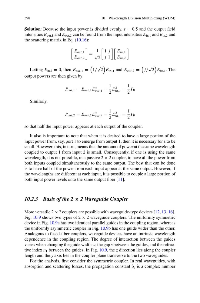
Solution: Because the input power is divided evenly, ε = 0.5 and the output field
intensities E out,1 and E out,2 can be found from the input intensities E in,1 and E in,2 and
the scattering matrix in Eq. (10.16):
E out,1
E out,2
=
1
√
2
1 j
j 1
E in,1
E in,2
Letting E in,2 = 0, then E out,1 =
1/
√
2
E in,1 and E out,2 =
j/
√
2
E in,1 . The
output powers are then given by
P out,1 = E out,1 E
∗
out,1 =
1
2
E
2
in,1 =
1
2
P 0
Similarly,
P out,2 = E out,2 E
∗
out,2 =
1
2
E
2
in,1 =
1
2
P 0
so that half the input power appears at each output of the coupler.
It also is important to note that when it is desired to have a large portion of the
input power from, say, port 1 to emerge from output 1, then it is necessary for ε to be
small. However, this, in turn, means that the amount of power at the same wavelength
coupled to output 1 from input 2 is small. Consequently, if one is using the same
wavelength, it is not possible, in a passive 2 × 2 coupler, to have all the power from
both inputs coupled simultaneously to the same output. The best that can be done
is to have half of the power from each input appear at the same output. However, if
the wavelengths are different at each input, it is possible to couple a large portion of
both input power levels onto the same output fiber [11].
10.2.3 Basis of the 2 × 2 Waveguide Coupler
More versatile 2 × 2 couplers are possible with waveguide-type devices [12, 13, 16].
Fig. 10.9 shows two types of 2 × 2 waveguide couplers. The uniformly symmetric
device in Fig. 10.9a has two identical parallel guides in the coupling region, whereas
the uniformly asymmetric coupler in Fig. 10.9b has one guide wider than the other.
Analogous to fused-fiber couplers, waveguide devices have an intrinsic wavelength
dependence in the coupling region. The degree of interaction between the guides
varies when changing the guide width w, the gap s between the guides, and the refractive index n 1 between the guides. In Fig. 10.9, the z direction lies along the coupler
length and the y axis lies in the coupler plane transverse to the two waveguides.
For the analysis, first consider the symmetric coupler. In real waveguides, with
absorption and scattering losses, the propagation constant β z is a complex number
10 Wavelength Division Multiplexing (WDM)
Solution: Because the input power is divided evenly, ε = 0.5 and the output field
intensities E out,1 and E out,2 can be found from the input intensities E in,1 and E in,2 and
the scattering matrix in Eq. (10.16):
E out,1
E out,2
=
1
√
2
1 j
j 1
E in,1
E in,2
Letting E in,2 = 0, then E out,1 =
1/
√
2
E in,1 and E out,2 =
j/
√
2
E in,1 . The
output powers are then given by
P out,1 = E out,1 E
∗
out,1 =
1
2
E
2
in,1 =
1
2
P 0
Similarly,
P out,2 = E out,2 E
∗
out,2 =
1
2
E
2
in,1 =
1
2
P 0
so that half the input power appears at each output of the coupler.
It also is important to note that when it is desired to have a large portion of the
input power from, say, port 1 to emerge from output 1, then it is necessary for ε to be
small. However, this, in turn, means that the amount of power at the same wavelength
coupled to output 1 from input 2 is small. Consequently, if one is using the same
wavelength, it is not possible, in a passive 2 × 2 coupler, to have all the power from
both inputs coupled simultaneously to the same output. The best that can be done
is to have half of the power from each input appear at the same output. However, if
the wavelengths are different at each input, it is possible to couple a large portion of
both input power levels onto the same output fiber [11].
10.2.3 Basis of the 2 × 2 Waveguide Coupler
More versatile 2 × 2 couplers are possible with waveguide-type devices [12, 13, 16].
Fig. 10.9 shows two types of 2 × 2 waveguide couplers. The uniformly symmetric
device in Fig. 10.9a has two identical parallel guides in the coupling region, whereas
the uniformly asymmetric coupler in Fig. 10.9b has one guide wider than the other.
Analogous to fused-fiber couplers, waveguide devices have an intrinsic wavelength
dependence in the coupling region. The degree of interaction between the guides
varies when changing the guide width w, the gap s between the guides, and the refractive index n 1 between the guides. In Fig. 10.9, the z direction lies along the coupler
length and the y axis lies in the coupler plane transverse to the two waveguides.
For the analysis, first consider the symmetric coupler. In real waveguides, with
absorption and scattering losses, the propagation constant β z is a complex number