

10.2 Passive Optical Couplers
397
I 0 = b
∗
1 b 1 + b
∗
2 b 2 = I i = a
∗
1 a 1 + a
∗
2 a 2
or b
+ b = a
+ a
(10.10)
where the superscript * means the complex conjugate and the superscript + indicates
the transpose conjugate. Substituting Eqs. (10.8) and (10.9) into Eq. (10.10) yields
the following set of three equations:
s
∗
11 s 11 + s
∗
12 s 12 = 1
(10.11)
s
∗
11 s 12 + s
∗
12 s 22 = 0
(10.12)
s
∗
22 s 22 + s
∗
12 s 12 = 1
(10.13)
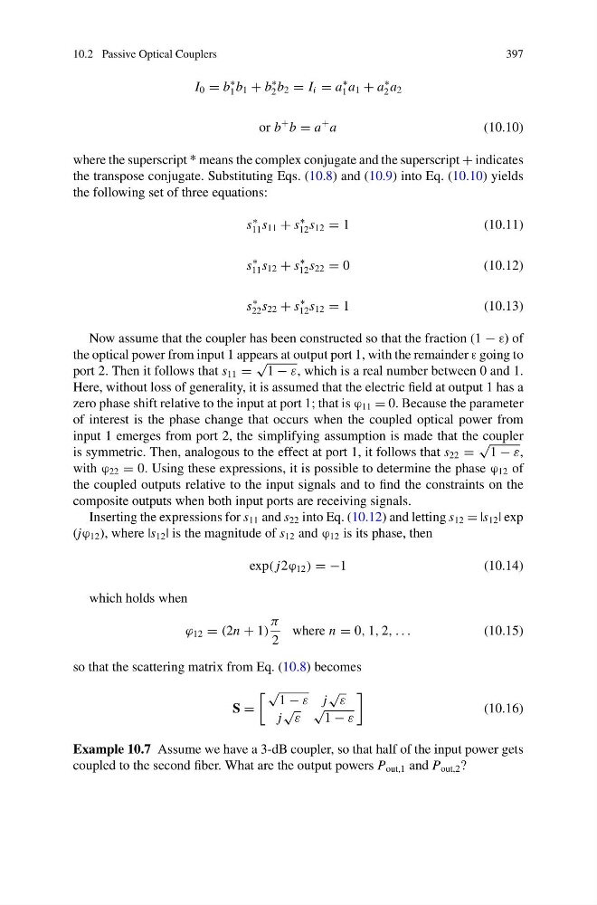
Now assume that the coupler has been constructed so that the fraction (1 − ε) of
the optical power from input 1 appears at output port 1, with the remainder ε going to
port 2. Then it follows that s 11 =
√
1 − ε, which is a real number between 0 and 1.
Here, without loss of generality, it is assumed that the electric field at output 1 has a
zero phase shift relative to the input at port 1; that is ϕ 11 = 0. Because the parameter
of interest is the phase change that occurs when the coupled optical power from
input 1 emerges from port 2, the simplifying assumption is made that the coupler
is symmetric. Then, analogous to the effect at port 1, it follows that s 22 =
√
1 − ε,
with ϕ 22 = 0. Using these expressions, it is possible to determine the phase ϕ 12 of
the coupled outputs relative to the input signals and to find the constraints on the
composite outputs when both input ports are receiving signals.
Inserting the expressions for s 11 and s 22 into Eq. (10.12) and letting s 12 = |s 12 | exp
(jϕ 12 ), where |s 12 | is the magnitude of s 12 and ϕ 12 is its phase, then
exp( j2ϕ 12 ) = −1
(10.14)
which holds when
ϕ 12 = (2n + 1)
π
2
where n = 0, 1, 2, . . .
(10.15)
so that the scattering matrix from Eq. (10.8) becomes
S =
√
1 − ε j
√ ε
j
√ ε
√
1 − ε
(10.16)
Example 10.7 Assume we have a 3-dB coupler, so that half of the input power gets
coupled to the second fiber. What are the output powers P out,1 and P out,2 ?
397
I 0 = b
∗
1 b 1 + b
∗
2 b 2 = I i = a
∗
1 a 1 + a
∗
2 a 2
or b
+ b = a
+ a
(10.10)
where the superscript * means the complex conjugate and the superscript + indicates
the transpose conjugate. Substituting Eqs. (10.8) and (10.9) into Eq. (10.10) yields
the following set of three equations:
s
∗
11 s 11 + s
∗
12 s 12 = 1
(10.11)
s
∗
11 s 12 + s
∗
12 s 22 = 0
(10.12)
s
∗
22 s 22 + s
∗
12 s 12 = 1
(10.13)
Now assume that the coupler has been constructed so that the fraction (1 − ε) of
the optical power from input 1 appears at output port 1, with the remainder ε going to
port 2. Then it follows that s 11 =
√
1 − ε, which is a real number between 0 and 1.
Here, without loss of generality, it is assumed that the electric field at output 1 has a
zero phase shift relative to the input at port 1; that is ϕ 11 = 0. Because the parameter
of interest is the phase change that occurs when the coupled optical power from
input 1 emerges from port 2, the simplifying assumption is made that the coupler
is symmetric. Then, analogous to the effect at port 1, it follows that s 22 =
√
1 − ε,
with ϕ 22 = 0. Using these expressions, it is possible to determine the phase ϕ 12 of
the coupled outputs relative to the input signals and to find the constraints on the
composite outputs when both input ports are receiving signals.
Inserting the expressions for s 11 and s 22 into Eq. (10.12) and letting s 12 = |s 12 | exp
(jϕ 12 ), where |s 12 | is the magnitude of s 12 and ϕ 12 is its phase, then
exp( j2ϕ 12 ) = −1
(10.14)
which holds when
ϕ 12 = (2n + 1)
π
2
where n = 0, 1, 2, . . .
(10.15)
so that the scattering matrix from Eq. (10.8) becomes
S =
√
1 − ε j
√ ε
j
√ ε
√
1 − ε
(10.16)
Example 10.7 Assume we have a 3-dB coupler, so that half of the input power gets
coupled to the second fiber. What are the output powers P out,1 and P out,2 ?