

396
10 Wavelength Division Multiplexing (WDM)
10.2.2 Scattering Matrix Analyses of Couplers
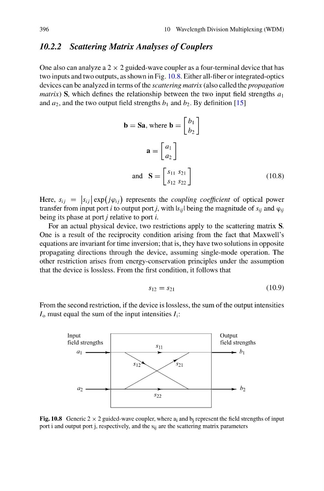
One also can analyze a 2 × 2 guided-wave coupler as a four-terminal device that has
two inputs and two outputs, as shown in Fig. 10.8. Either all-fiber or integrated-optics
devices can be analyzed in terms of the scattering matrix (also called the propagation
matrix) S, which defines the relationship between the two input field strengths a 1
and a 2 , and the two output field strengths b 1 and b 2 . By definition [15]
b = Sa, where b =
b 1
b 2
a =
a 1
a 2
and S =
s 11 s 21
s 12 s 22
(10.8)
Here, s i j =
s i j
exp
jϕ i j
represents the coupling coefficient of optical power
transfer from input port i to output port j, with |s ij | being the magnitude of s ij and ϕ ij
being its phase at port j relative to port i.
For an actual physical device, two restrictions apply to the scattering matrix S.
One is a result of the reciprocity condition arising from the fact that Maxwell’s
equations are invariant for time inversion; that is, they have two solutions in opposite
propagating directions through the device, assuming single-mode operation. The
other restriction arises from energy-conservation principles under the assumption
that the device is lossless. From the first condition, it follows that
s 12 = s 21
(10.9)
From the second restriction, if the device is lossless, the sum of the output intensities
I o must equal the sum of the input intensities I i :
Fig. 10.8 Generic 2 × 2 guided-wave coupler, where a i and b j represent the field strengths of input
port i and output port j, respectively, and the s ij are the scattering matrix parameters
10 Wavelength Division Multiplexing (WDM)
10.2.2 Scattering Matrix Analyses of Couplers
One also can analyze a 2 × 2 guided-wave coupler as a four-terminal device that has
two inputs and two outputs, as shown in Fig. 10.8. Either all-fiber or integrated-optics
devices can be analyzed in terms of the scattering matrix (also called the propagation
matrix) S, which defines the relationship between the two input field strengths a 1
and a 2 , and the two output field strengths b 1 and b 2 . By definition [15]
b = Sa, where b =
b 1
b 2
a =
a 1
a 2
and S =
s 11 s 21
s 12 s 22
(10.8)
Here, s i j =
s i j
exp
jϕ i j
represents the coupling coefficient of optical power
transfer from input port i to output port j, with |s ij | being the magnitude of s ij and ϕ ij
being its phase at port j relative to port i.
For an actual physical device, two restrictions apply to the scattering matrix S.
One is a result of the reciprocity condition arising from the fact that Maxwell’s
equations are invariant for time inversion; that is, they have two solutions in opposite
propagating directions through the device, assuming single-mode operation. The
other restriction arises from energy-conservation principles under the assumption
that the device is lossless. From the first condition, it follows that
s 12 = s 21
(10.9)
From the second restriction, if the device is lossless, the sum of the output intensities
I o must equal the sum of the input intensities I i :
Fig. 10.8 Generic 2 × 2 guided-wave coupler, where a i and b j represent the field strengths of input
port i and output port j, respectively, and the s ij are the scattering matrix parameters