

10.2 Passive Optical Couplers
395
5.5 mm
35 mm
Tap coupler body
Input
flylead
Tap
flylead
Throughput
flylead
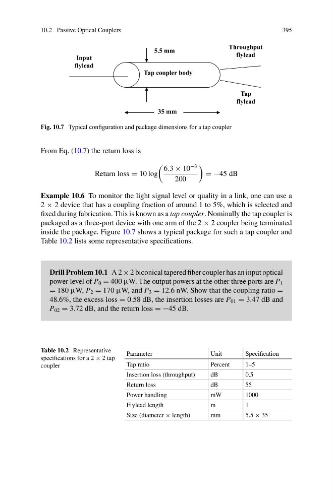
Fig. 10.7 Typical configuration and package dimensions for a tap coupler
From Eq. (10.7) the return loss is
Return loss = 10 log
6.3 × 10
−3
200
= −45 dB
Example 10.6 To monitor the light signal level or quality in a link, one can use a
2 × 2 device that has a coupling fraction of around 1 to 5%, which is selected and
fixed during fabrication. This is known as a tap coupler. Nominally the tap coupler is
packaged as a three-port device with one arm of the 2 × 2 coupler being terminated
inside the package. Figure 10.7 shows a typical package for such a tap coupler and
Table 10.2 lists some representative specifications.
Drill Problem 10.1 A 2 × 2 biconical tapered fiber coupler has an input optical
power level of P 0 = 400 μW. The output powers at the other three ports are P 1
= 180 μW, P 2 = 170 μW, and P 3 = 12.6 nW. Show that the coupling ratio =
48.6%, the excess loss = 0.58 dB, the insertion losses are P 01 = 3.47 dB and
P 02 = 3.72 dB, and the return loss = −45 dB.
Table 10.2 Representative
specifications for a 2 × 2 tap
coupler
Parameter
Unit
Specification
Tap ratio
Percent
1–5
Insertion loss (throughput)
dB
0.5
Return loss
dB
55
Power handling
mW
1000
Flylead length
m
1
Size (diameter × length)
mm
5.5 × 35
395
5.5 mm
35 mm
Tap coupler body
Input
flylead
Tap
flylead
Throughput
flylead
Fig. 10.7 Typical configuration and package dimensions for a tap coupler
From Eq. (10.7) the return loss is
Return loss = 10 log
6.3 × 10
−3
200
= −45 dB
Example 10.6 To monitor the light signal level or quality in a link, one can use a
2 × 2 device that has a coupling fraction of around 1 to 5%, which is selected and
fixed during fabrication. This is known as a tap coupler. Nominally the tap coupler is
packaged as a three-port device with one arm of the 2 × 2 coupler being terminated
inside the package. Figure 10.7 shows a typical package for such a tap coupler and
Table 10.2 lists some representative specifications.
Drill Problem 10.1 A 2 × 2 biconical tapered fiber coupler has an input optical
power level of P 0 = 400 μW. The output powers at the other three ports are P 1
= 180 μW, P 2 = 170 μW, and P 3 = 12.6 nW. Show that the coupling ratio =
48.6%, the excess loss = 0.58 dB, the insertion losses are P 01 = 3.47 dB and
P 02 = 3.72 dB, and the return loss = −45 dB.
Table 10.2 Representative
specifications for a 2 × 2 tap
coupler
Parameter
Unit
Specification
Tap ratio
Percent
1–5
Insertion loss (throughput)
dB
0.5
Return loss
dB
55
Power handling
mW
1000
Flylead length
m
1
Size (diameter × length)
mm
5.5 × 35