

394
10 Wavelength Division Multiplexing (WDM)
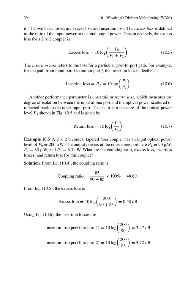
it. The two basic losses are excess loss and insertion loss. The excess loss is defined
as the ratio of the input power to the total output power. Thus in decibels, the excess
loss for a 2 × 2 coupler is
Excess loss = 10 log
P 0
P 1 + P 2
(10.5)
The insertion loss refers to the loss for a particular port-to-port path. For example,
for the path from input port i to output port j, the insertion loss in decibels is
Insertion loss = P i j = 10 log
P i
P j
(10.6)
Another performance parameter is crosstalk or return loss, which measures the
degree of isolation between the input at one port and the optical power scattered or
reflected back to the other input port. That is, it is a measure of the optical power
level P 3 shown in Fig. 10.5 and is given by
Return loss = 10 log
P 3
P 0
(10.7)
Example 10.5 A 2 × 2 biconical tapered fiber coupler has an input optical power
level of P 0 = 200 μW. The output powers at the other three ports are P 1 = 90 μW,
P 2 = 85 μW, and P 3 = 6.3 nW. What are the coupling ratio, excess loss, insertion
losses, and return loss for this coupler?
Solution: From Eq. (10.4), the coupling ratio is
Coupling ratio =
85
90 + 85
× 100% = 48.6%
From Eq. (10.5), the excess loss is
Excess loss = 10 log
200
90 + 85
= 0.58 dB
Using Eq. (10.6), the insertion losses are
Insertion loss(port 0 to port 1) = 10 log
200
90
= 3.47 dB
Insertion loss(port 0 to port 2) = 10 log
200
85
= 3.72 dB
10 Wavelength Division Multiplexing (WDM)
it. The two basic losses are excess loss and insertion loss. The excess loss is defined
as the ratio of the input power to the total output power. Thus in decibels, the excess
loss for a 2 × 2 coupler is
Excess loss = 10 log
P 0
P 1 + P 2
(10.5)
The insertion loss refers to the loss for a particular port-to-port path. For example,
for the path from input port i to output port j, the insertion loss in decibels is
Insertion loss = P i j = 10 log
P i
P j
(10.6)
Another performance parameter is crosstalk or return loss, which measures the
degree of isolation between the input at one port and the optical power scattered or
reflected back to the other input port. That is, it is a measure of the optical power
level P 3 shown in Fig. 10.5 and is given by
Return loss = 10 log
P 3
P 0
(10.7)
Example 10.5 A 2 × 2 biconical tapered fiber coupler has an input optical power
level of P 0 = 200 μW. The output powers at the other three ports are P 1 = 90 μW,
P 2 = 85 μW, and P 3 = 6.3 nW. What are the coupling ratio, excess loss, insertion
losses, and return loss for this coupler?
Solution: From Eq. (10.4), the coupling ratio is
Coupling ratio =
85
90 + 85
× 100% = 48.6%
From Eq. (10.5), the excess loss is
Excess loss = 10 log
200
90 + 85
= 0.58 dB
Using Eq. (10.6), the insertion losses are
Insertion loss(port 0 to port 1) = 10 log
200
90
= 3.47 dB
Insertion loss(port 0 to port 2) = 10 log
200
85
= 3.72 dB