

10.2 Passive Optical Couplers
393
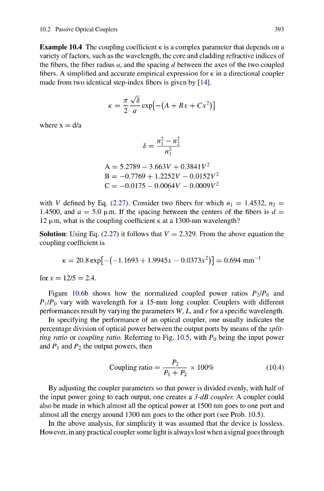
Example 10.4 The coupling coefficient κ is a complex parameter that depends on a
variety of factors, such as the wavelength, the core and cladding refractive indices of
the fibers, the fiber radius a, and the spacing d between the axes of the two coupled
fibers. A simplified and accurate empirical expression for κ in a directional coupler
made from two identical step-index fibers is given by [14].
κ =
π
2
√
δ
a
exp
−
A + Bx + C x
2
where x = d/a
δ =
n
2
1 − n
2
2
n
2
1
A = 5.2789 − 3.663V + 0.3841V
2
B = −0.7769 + 1.2252V − 0.0152V
2
C = −0.0175 − 0.0064V − 0.0009V
2
with V defined by Eq. (2.27). Consider two fibers for which n 1 = 1.4532, n 2 =
1.4500, and a = 5.0 μm. If the spacing between the centers of the fibers is d =
12 μm, what is the coupling coefficient κ at a 1300-nm wavelength?
Solution: Using Eq. (2.27) it follows that V = 2.329. From the above equation the
coupling coefficient is
κ = 20.8 exp
−
−1.1693 + 1.9945x − 0.0373x
2
= 0.694 mm
−1
for x = 12/5 = 2.4.
Figure 10.6b shows how the normalized coupled power ratios P 2 /P 0 and
P 1 /P 0 vary with wavelength for a 15-mm long coupler. Couplers with different
performances result by varying the parameters W, L, and r for a specific wavelength.
In specifying the performance of an optical coupler, one usually indicates the
percentage division of optical power between the output ports by means of the splitting ratio or coupling ratio. Referring to Fig. 10.5, with P 0 being the input power
and P 1 and P 2 the output powers, then
Coupling ratio =
P 2
P 1 + P 2
× 100%
(10.4)
By adjusting the coupler parameters so that power is divided evenly, with half of
the input power going to each output, one creates a 3-dB coupler. A coupler could
also be made in which almost all the optical power at 1500 nm goes to one port and
almost all the energy around 1300 nm goes to the other port (see Prob. 10.5).
In the above analysis, for simplicity it was assumed that the device is lossless.
However, in any practical coupler some light is always lost when a signal goes through
393
Example 10.4 The coupling coefficient κ is a complex parameter that depends on a
variety of factors, such as the wavelength, the core and cladding refractive indices of
the fibers, the fiber radius a, and the spacing d between the axes of the two coupled
fibers. A simplified and accurate empirical expression for κ in a directional coupler
made from two identical step-index fibers is given by [14].
κ =
π
2
√
δ
a
exp
−
A + Bx + C x
2
where x = d/a
δ =
n
2
1 − n
2
2
n
2
1
A = 5.2789 − 3.663V + 0.3841V
2
B = −0.7769 + 1.2252V − 0.0152V
2
C = −0.0175 − 0.0064V − 0.0009V
2
with V defined by Eq. (2.27). Consider two fibers for which n 1 = 1.4532, n 2 =
1.4500, and a = 5.0 μm. If the spacing between the centers of the fibers is d =
12 μm, what is the coupling coefficient κ at a 1300-nm wavelength?
Solution: Using Eq. (2.27) it follows that V = 2.329. From the above equation the
coupling coefficient is
κ = 20.8 exp
−
−1.1693 + 1.9945x − 0.0373x
2
= 0.694 mm
−1
for x = 12/5 = 2.4.
Figure 10.6b shows how the normalized coupled power ratios P 2 /P 0 and
P 1 /P 0 vary with wavelength for a 15-mm long coupler. Couplers with different
performances result by varying the parameters W, L, and r for a specific wavelength.
In specifying the performance of an optical coupler, one usually indicates the
percentage division of optical power between the output ports by means of the splitting ratio or coupling ratio. Referring to Fig. 10.5, with P 0 being the input power
and P 1 and P 2 the output powers, then
Coupling ratio =
P 2
P 1 + P 2
× 100%
(10.4)
By adjusting the coupler parameters so that power is divided evenly, with half of
the input power going to each output, one creates a 3-dB coupler. A coupler could
also be made in which almost all the optical power at 1500 nm goes to one port and
almost all the energy around 1300 nm goes to the other port (see Prob. 10.5).
In the above analysis, for simplicity it was assumed that the device is lossless.
However, in any practical coupler some light is always lost when a signal goes through