

392
10 Wavelength Division Multiplexing (WDM)
P 2 = P 0 sin
2
(κz)
(10.2)
where κ is the coupling coefficient describing the interaction between the fields in
the two fibers. By conservation of power, for identical-core fibers it follows that
P 1 = P 0 − P 2 = P 0
1 − sin
2
(κz)
= P 0 cos
2
(κz)
(10.3)
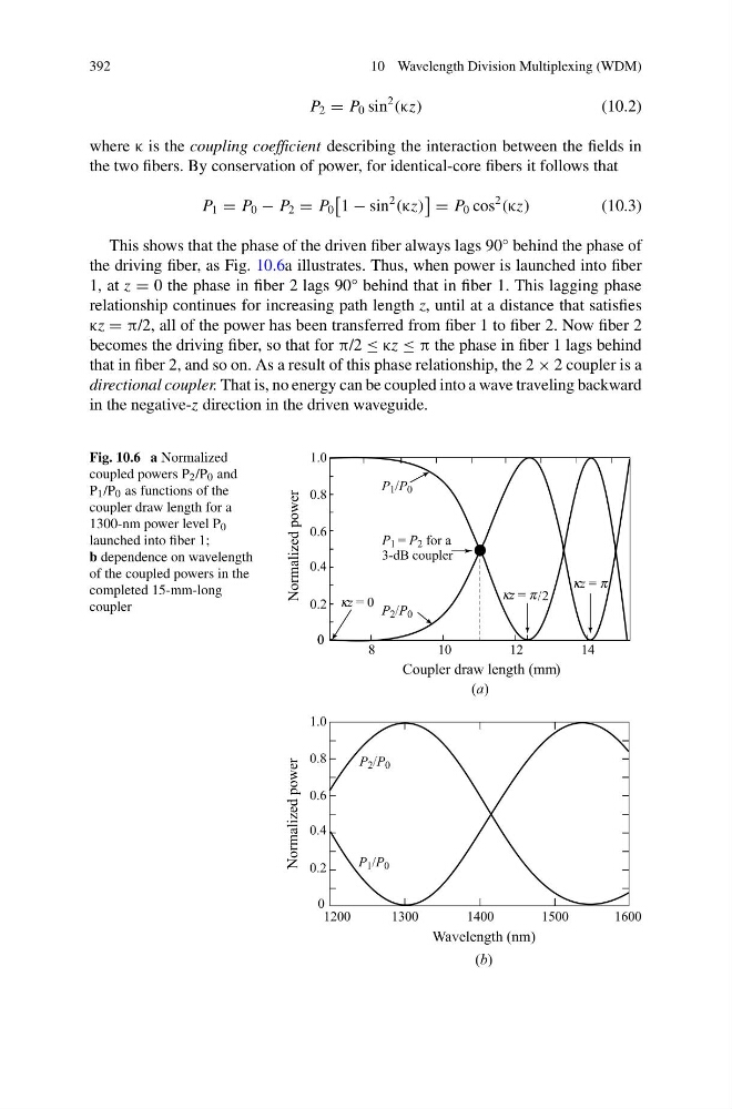
This shows that the phase of the driven fiber always lags 90° behind the phase of
the driving fiber, as Fig. 10.6a illustrates. Thus, when power is launched into fiber
1, at z = 0 the phase in fiber 2 lags 90° behind that in fiber 1. This lagging phase
relationship continues for increasing path length z, until at a distance that satisfies
κz = π/2, all of the power has been transferred from fiber 1 to fiber 2. Now fiber 2
becomes the driving fiber, so that for π/2 ≤ κz ≤ π the phase in fiber 1 lags behind
that in fiber 2, and so on. As a result of this phase relationship, the 2 × 2 coupler is a
directional coupler. That is, no energy can be coupled into a wave traveling backward
in the negative-z direction in the driven waveguide.
Fig. 10.6 a Normalized
coupled powers P 2 /P 0 and
P 1 /P 0 as functions of the
coupler draw length for a
1300-nm power level P 0
launched into fiber 1;
b dependence on wavelength
of the coupled powers in the
completed 15-mm-long
coupler
10 Wavelength Division Multiplexing (WDM)
P 2 = P 0 sin
2
(κz)
(10.2)
where κ is the coupling coefficient describing the interaction between the fields in
the two fibers. By conservation of power, for identical-core fibers it follows that
P 1 = P 0 − P 2 = P 0
1 − sin
2
(κz)
= P 0 cos
2
(κz)
(10.3)
This shows that the phase of the driven fiber always lags 90° behind the phase of
the driving fiber, as Fig. 10.6a illustrates. Thus, when power is launched into fiber
1, at z = 0 the phase in fiber 2 lags 90° behind that in fiber 1. This lagging phase
relationship continues for increasing path length z, until at a distance that satisfies
κz = π/2, all of the power has been transferred from fiber 1 to fiber 2. Now fiber 2
becomes the driving fiber, so that for π/2 ≤ κz ≤ π the phase in fiber 1 lags behind
that in fiber 2, and so on. As a result of this phase relationship, the 2 × 2 coupler is a
directional coupler. That is, no energy can be coupled into a wave traveling backward
in the negative-z direction in the driven waveguide.
Fig. 10.6 a Normalized
coupled powers P 2 /P 0 and
P 1 /P 0 as functions of the
coupler draw length for a
1300-nm power level P 0
launched into fiber 1;
b dependence on wavelength
of the coupled powers in the
completed 15-mm-long
coupler