

10.2 Passive Optical Couplers
391
Optical power
coupling
Thinned
core-cladding
region
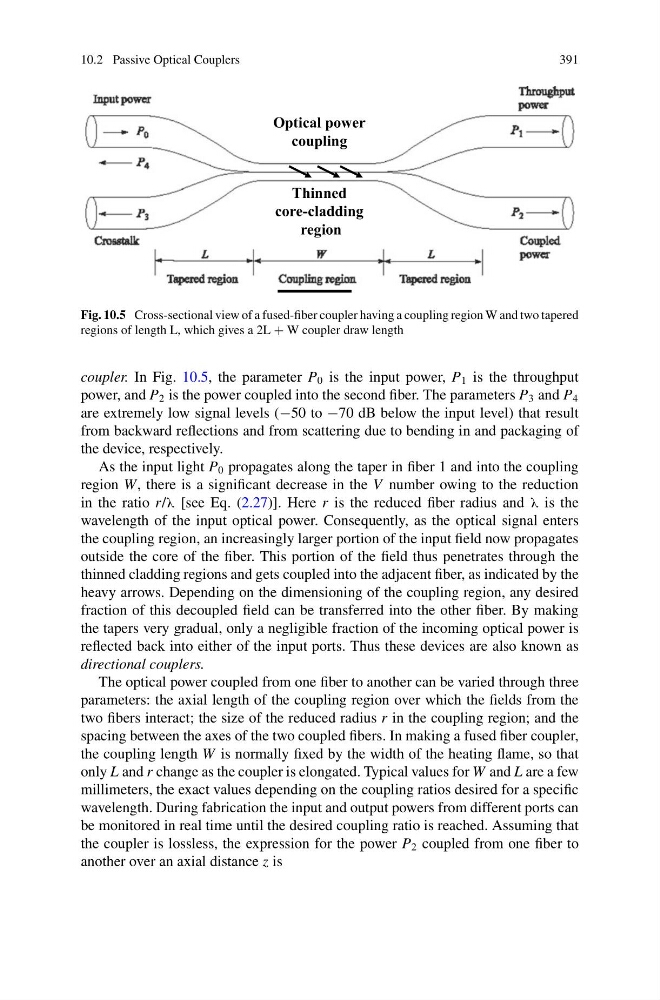
Fig. 10.5 Cross-sectional view of a fused-fiber coupler having a coupling region W and two tapered
regions of length L, which gives a 2L + W coupler draw length
coupler. In Fig. 10.5, the parameter P 0 is the input power, P 1 is the throughput
power, and P 2 is the power coupled into the second fiber. The parameters P 3 and P 4
are extremely low signal levels (−50 to −70 dB below the input level) that result
from backward reflections and from scattering due to bending in and packaging of
the device, respectively.
As the input light P 0 propagates along the taper in fiber 1 and into the coupling
region W, there is a significant decrease in the V number owing to the reduction
in the ratio r/λ [see Eq. (2.27)]. Here r is the reduced fiber radius and λ is the
wavelength of the input optical power. Consequently, as the optical signal enters
the coupling region, an increasingly larger portion of the input field now propagates
outside the core of the fiber. This portion of the field thus penetrates through the
thinned cladding regions and gets coupled into the adjacent fiber, as indicated by the
heavy arrows. Depending on the dimensioning of the coupling region, any desired
fraction of this decoupled field can be transferred into the other fiber. By making
the tapers very gradual, only a negligible fraction of the incoming optical power is
reflected back into either of the input ports. Thus these devices are also known as
directional couplers.
The optical power coupled from one fiber to another can be varied through three
parameters: the axial length of the coupling region over which the fields from the
two fibers interact; the size of the reduced radius r in the coupling region; and the
spacing between the axes of the two coupled fibers. In making a fused fiber coupler,
the coupling length W is normally fixed by the width of the heating flame, so that
only L and r change as the coupler is elongated. Typical values for W and L are a few
millimeters, the exact values depending on the coupling ratios desired for a specific
wavelength. During fabrication the input and output powers from different ports can
be monitored in real time until the desired coupling ratio is reached. Assuming that
the coupler is lossless, the expression for the power P 2 coupled from one fiber to
another over an axial distance z is
391
Optical power
coupling
Thinned
core-cladding
region
Fig. 10.5 Cross-sectional view of a fused-fiber coupler having a coupling region W and two tapered
regions of length L, which gives a 2L + W coupler draw length
coupler. In Fig. 10.5, the parameter P 0 is the input power, P 1 is the throughput
power, and P 2 is the power coupled into the second fiber. The parameters P 3 and P 4
are extremely low signal levels (−50 to −70 dB below the input level) that result
from backward reflections and from scattering due to bending in and packaging of
the device, respectively.
As the input light P 0 propagates along the taper in fiber 1 and into the coupling
region W, there is a significant decrease in the V number owing to the reduction
in the ratio r/λ [see Eq. (2.27)]. Here r is the reduced fiber radius and λ is the
wavelength of the input optical power. Consequently, as the optical signal enters
the coupling region, an increasingly larger portion of the input field now propagates
outside the core of the fiber. This portion of the field thus penetrates through the
thinned cladding regions and gets coupled into the adjacent fiber, as indicated by the
heavy arrows. Depending on the dimensioning of the coupling region, any desired
fraction of this decoupled field can be transferred into the other fiber. By making
the tapers very gradual, only a negligible fraction of the incoming optical power is
reflected back into either of the input ports. Thus these devices are also known as
directional couplers.
The optical power coupled from one fiber to another can be varied through three
parameters: the axial length of the coupling region over which the fields from the
two fibers interact; the size of the reduced radius r in the coupling region; and the
spacing between the axes of the two coupled fibers. In making a fused fiber coupler,
the coupling length W is normally fixed by the width of the heating flame, so that
only L and r change as the coupler is elongated. Typical values for W and L are a few
millimeters, the exact values depending on the coupling ratios desired for a specific
wavelength. During fabrication the input and output powers from different ports can
be monitored in real time until the desired coupling ratio is reached. Assuming that
the coupler is lossless, the expression for the power P 2 coupled from one fiber to
another over an axial distance z is