

390
10 Wavelength Division Multiplexing (WDM)
Star
coupler
P 1
P k
P N
P 2
1
2
•
•
•
•
•
•
•
•
k
N
Output from
each port is
N
P
P
P
N
.
.
.
1
2
1
Inputs
Outputs
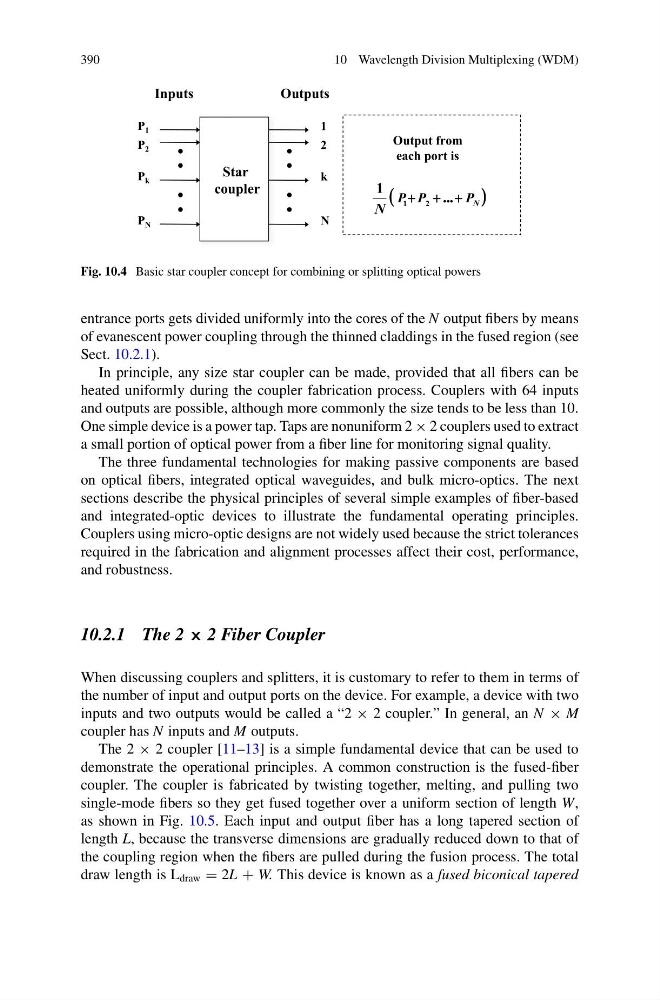
Fig. 10.4 Basic star coupler concept for combining or splitting optical powers
entrance ports gets divided uniformly into the cores of the N output fibers by means
of evanescent power coupling through the thinned claddings in the fused region (see
Sect. 10.2.1).
In principle, any size star coupler can be made, provided that all fibers can be
heated uniformly during the coupler fabrication process. Couplers with 64 inputs
and outputs are possible, although more commonly the size tends to be less than 10.
One simple device is a power tap. Taps are nonuniform 2 × 2 couplers used to extract
a small portion of optical power from a fiber line for monitoring signal quality.
The three fundamental technologies for making passive components are based
on optical fibers, integrated optical waveguides, and bulk micro-optics. The next
sections describe the physical principles of several simple examples of fiber-based
and integrated-optic devices to illustrate the fundamental operating principles.
Couplers using micro-optic designs are not widely used because the strict tolerances
required in the fabrication and alignment processes affect their cost, performance,
and robustness.
10.2.1 The 2 × 2 Fiber Coupler
When discussing couplers and splitters, it is customary to refer to them in terms of
the number of input and output ports on the device. For example, a device with two
inputs and two outputs would be called a “2 × 2 coupler.” In general, an N × M
coupler has N inputs and M outputs.
The 2 × 2 coupler [11–13] is a simple fundamental device that can be used to
demonstrate the operational principles. A common construction is the fused-fiber
coupler. The coupler is fabricated by twisting together, melting, and pulling two
single-mode fibers so they get fused together over a uniform section of length W,
as shown in Fig. 10.5. Each input and output fiber has a long tapered section of
length L, because the transverse dimensions are gradually reduced down to that of
the coupling region when the fibers are pulled during the fusion process. The total
draw length is L draw = 2L + W. This device is known as a fused biconical tapered
10 Wavelength Division Multiplexing (WDM)
Star
coupler
P 1
P k
P N
P 2
1
2
•
•
•
•
•
•
•
•
k
N
Output from
each port is
N
P
P
P
N
.
.
.
1
2
1
Inputs
Outputs
Fig. 10.4 Basic star coupler concept for combining or splitting optical powers
entrance ports gets divided uniformly into the cores of the N output fibers by means
of evanescent power coupling through the thinned claddings in the fused region (see
Sect. 10.2.1).
In principle, any size star coupler can be made, provided that all fibers can be
heated uniformly during the coupler fabrication process. Couplers with 64 inputs
and outputs are possible, although more commonly the size tends to be less than 10.
One simple device is a power tap. Taps are nonuniform 2 × 2 couplers used to extract
a small portion of optical power from a fiber line for monitoring signal quality.
The three fundamental technologies for making passive components are based
on optical fibers, integrated optical waveguides, and bulk micro-optics. The next
sections describe the physical principles of several simple examples of fiber-based
and integrated-optic devices to illustrate the fundamental operating principles.
Couplers using micro-optic designs are not widely used because the strict tolerances
required in the fabrication and alignment processes affect their cost, performance,
and robustness.
10.2.1 The 2 × 2 Fiber Coupler
When discussing couplers and splitters, it is customary to refer to them in terms of
the number of input and output ports on the device. For example, a device with two
inputs and two outputs would be called a “2 × 2 coupler.” In general, an N × M
coupler has N inputs and M outputs.
The 2 × 2 coupler [11–13] is a simple fundamental device that can be used to
demonstrate the operational principles. A common construction is the fused-fiber
coupler. The coupler is fabricated by twisting together, melting, and pulling two
single-mode fibers so they get fused together over a uniform section of length W,
as shown in Fig. 10.5. Each input and output fiber has a long tapered section of
length L, because the transverse dimensions are gradually reduced down to that of
the coupling region when the fibers are pulled during the fusion process. The total
draw length is L draw = 2L + W. This device is known as a fused biconical tapered