

10.1 Concepts of WDM
389
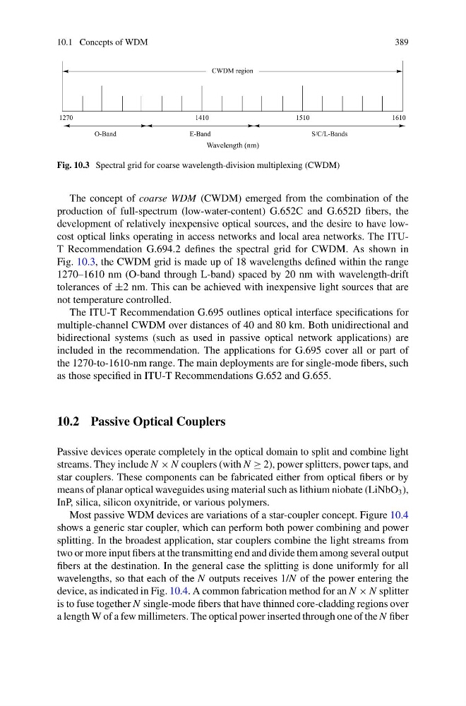
Fig. 10.3 Spectral grid for coarse wavelength-division multiplexing (CWDM)
The concept of coarse WDM (CWDM) emerged from the combination of the
production of full-spectrum (low-water-content) G.652C and G.652D fibers, the
development of relatively inexpensive optical sources, and the desire to have lowcost optical links operating in access networks and local area networks. The ITUT Recommendation G.694.2 defines the spectral grid for CWDM. As shown in
Fig. 10.3, the CWDM grid is made up of 18 wavelengths defined within the range
1270–1610 nm (O-band through L-band) spaced by 20 nm with wavelength-drift
tolerances of ±2 nm. This can be achieved with inexpensive light sources that are
not temperature controlled.
The ITU-T Recommendation G.695 outlines optical interface specifications for
multiple-channel CWDM over distances of 40 and 80 km. Both unidirectional and
bidirectional systems (such as used in passive optical network applications) are
included in the recommendation. The applications for G.695 cover all or part of
the 1270-to-1610-nm range. The main deployments are for single-mode fibers, such
as those specified in ITU-T Recommendations G.652 and G.655.
10.2 Passive Optical Couplers
Passive devices operate completely in the optical domain to split and combine light
streams. They include N × N couplers (with N ≥ 2), power splitters, power taps, and
star couplers. These components can be fabricated either from optical fibers or by
means of planar optical waveguides using material such as lithium niobate (LiNbO 3 ),
InP, silica, silicon oxynitride, or various polymers.
Most passive WDM devices are variations of a star-coupler concept. Figure 10.4
shows a generic star coupler, which can perform both power combining and power
splitting. In the broadest application, star couplers combine the light streams from
two or more input fibers at the transmitting end and divide them among several output
fibers at the destination. In the general case the splitting is done uniformly for all
wavelengths, so that each of the N outputs receives 1/N of the power entering the
device, as indicated in Fig. 10.4. A common fabrication method for an N × N splitter
is to fuse together N single-mode fibers that have thinned core-cladding regions over
a length W of a few millimeters. The optical power inserted through one of the N fiber
389
Fig. 10.3 Spectral grid for coarse wavelength-division multiplexing (CWDM)
The concept of coarse WDM (CWDM) emerged from the combination of the
production of full-spectrum (low-water-content) G.652C and G.652D fibers, the
development of relatively inexpensive optical sources, and the desire to have lowcost optical links operating in access networks and local area networks. The ITUT Recommendation G.694.2 defines the spectral grid for CWDM. As shown in
Fig. 10.3, the CWDM grid is made up of 18 wavelengths defined within the range
1270–1610 nm (O-band through L-band) spaced by 20 nm with wavelength-drift
tolerances of ±2 nm. This can be achieved with inexpensive light sources that are
not temperature controlled.
The ITU-T Recommendation G.695 outlines optical interface specifications for
multiple-channel CWDM over distances of 40 and 80 km. Both unidirectional and
bidirectional systems (such as used in passive optical network applications) are
included in the recommendation. The applications for G.695 cover all or part of
the 1270-to-1610-nm range. The main deployments are for single-mode fibers, such
as those specified in ITU-T Recommendations G.652 and G.655.
10.2 Passive Optical Couplers
Passive devices operate completely in the optical domain to split and combine light
streams. They include N × N couplers (with N ≥ 2), power splitters, power taps, and
star couplers. These components can be fabricated either from optical fibers or by
means of planar optical waveguides using material such as lithium niobate (LiNbO 3 ),
InP, silica, silicon oxynitride, or various polymers.
Most passive WDM devices are variations of a star-coupler concept. Figure 10.4
shows a generic star coupler, which can perform both power combining and power
splitting. In the broadest application, star couplers combine the light streams from
two or more input fibers at the transmitting end and divide them among several output
fibers at the destination. In the general case the splitting is done uniformly for all
wavelengths, so that each of the N outputs receives 1/N of the power entering the
device, as indicated in Fig. 10.4. A common fabrication method for an N × N splitter
is to fuse together N single-mode fibers that have thinned core-cladding regions over
a length W of a few millimeters. The optical power inserted through one of the N fiber