

8.2 Concepts of Link Power Penalties
333
3. Use connectors in which the end faces make physical contact (the so-called
PC connectors). Return losses of 25–40 dB have been measured with these
connectors.
4. Use optical isolators within the laser transmitter module. These devices easily
achieve 25-dB return losses, but they also can introduce up to 1 dB of forward
loss in the link.
Drill Problem 8.6 A GaAs optical source with a refractive index of 3.60 is
coupled to an optical fiber that has a core refractive index of 1.48. Show that
the optical return loss is 7.59 dB down from the signal power level incident on
the material interface (see Sect. 5.1).
8.3 Detection and Control of Errors
In any digital transmission system, errors are likely to occur even when there is
a sufficient SNR to provide a low bit-error rate. The acceptance of a certain level
of errors depends on the network user. For example, digitized speech or video can
tolerate occasional high error rates. However, applications such as financial transactions require almost completely error-free transmission. In this case, the transport
protocol of the network must compensate the difference between the desired and the
actual bit-error rates.
To control errors and to improve the reliability of a communication line, first it is
necessary to be able to detect the errors and then either to correct them or retransmit
the information. Error detection methods encode the information stream to have a
specific pattern. If segments in the received data stream violate this pattern, then
errors have occurred. Sections 8.3.1–8.3.3 discuss the concept and several popular
methods of error detection.
The two basic schemes for error correction are automatic repeat request (ARQ)
and forward error correction (FEC) [7, 30–32]. ARQ schemes have been used for
many years in applications such as computer communication links that use telephone
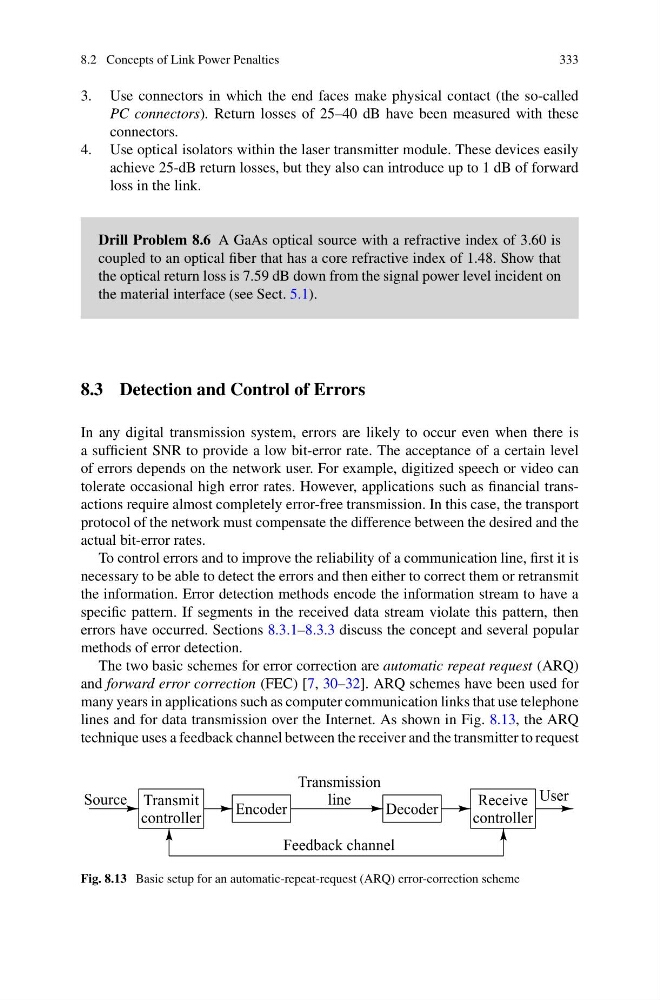
lines and for data transmission over the Internet. As shown in Fig. 8.13, the ARQ
technique uses a feedback channel between the receiver and the transmitter to request
Fig. 8.13 Basic setup for an automatic-repeat-request (ARQ) error-correction scheme
333
3. Use connectors in which the end faces make physical contact (the so-called
PC connectors). Return losses of 25–40 dB have been measured with these
connectors.
4. Use optical isolators within the laser transmitter module. These devices easily
achieve 25-dB return losses, but they also can introduce up to 1 dB of forward
loss in the link.
Drill Problem 8.6 A GaAs optical source with a refractive index of 3.60 is
coupled to an optical fiber that has a core refractive index of 1.48. Show that
the optical return loss is 7.59 dB down from the signal power level incident on
the material interface (see Sect. 5.1).
8.3 Detection and Control of Errors
In any digital transmission system, errors are likely to occur even when there is
a sufficient SNR to provide a low bit-error rate. The acceptance of a certain level
of errors depends on the network user. For example, digitized speech or video can
tolerate occasional high error rates. However, applications such as financial transactions require almost completely error-free transmission. In this case, the transport
protocol of the network must compensate the difference between the desired and the
actual bit-error rates.
To control errors and to improve the reliability of a communication line, first it is
necessary to be able to detect the errors and then either to correct them or retransmit
the information. Error detection methods encode the information stream to have a
specific pattern. If segments in the received data stream violate this pattern, then
errors have occurred. Sections 8.3.1–8.3.3 discuss the concept and several popular
methods of error detection.
The two basic schemes for error correction are automatic repeat request (ARQ)
and forward error correction (FEC) [7, 30–32]. ARQ schemes have been used for
many years in applications such as computer communication links that use telephone
lines and for data transmission over the Internet. As shown in Fig. 8.13, the ARQ
technique uses a feedback channel between the receiver and the transmitter to request
Fig. 8.13 Basic setup for an automatic-repeat-request (ARQ) error-correction scheme