

7.2 Performance Characteristics of Digital Receivers
285
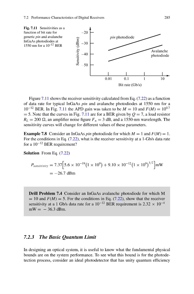
Fig. 7.11 Sensitivities as a
function of bit rate for
generic pin and avalanche
InGaAs photodiodes at
1550 nm for a 10 –12 BER
Figure 7.11 shows the receiver sensitivity calculated from Eq. (7.22) as a function
of data rate for typical InGaAs pin and avalanche photodiodes at 1550 nm for a
10
−12 BER. In Fig. 7.11 the APD gain was taken to be M = 10 and F(M) = 10
0.7
= 5. Note that the curves in Fig. 7.11 are for a BER given by Q = 7, a load resistor
R L = 200 , an amplifier noise figure F n = 3 dB, and a 1550-nm wavelength. The
sensitivity curves will change for different values of these parameters.
Example 7.8 Consider an InGaAs pin photodiode for which M = 1 and F(M) = 1.
For the conditions in Eq. (7.22), what is the receiver sensitivity at a 1-Gb/s data rate
for a 10
−12 BER requirement?
Solution From Eq. (7.22)
P sensitivit y = 7.37
5.6 × 10
−19
1 × 10
9
+ 9.10 × 10
−12
1 × 10
9
1/2
mW
= −26.7 dBm
Drill Problem 7.4 Consider an InGaAs avalanche photodiode for which M
= 10 and F(M) = 5. For the conditions in Eq. (7.22), show that the receiver
sensitivity at a 1 Gb/s data rate for a 10
−12 BER requirement is 2.32 × 10
−4
mW = − 36.3 dBm.
7.2.3 The Basic Quantum Limit
In designing an optical system, it is useful to know what the fundamental physical
bounds are on the system performance. To see what this bound is for the photodetection process, consider an ideal photodetector that has unity quantum efficiency
285
Fig. 7.11 Sensitivities as a
function of bit rate for
generic pin and avalanche
InGaAs photodiodes at
1550 nm for a 10 –12 BER
Figure 7.11 shows the receiver sensitivity calculated from Eq. (7.22) as a function
of data rate for typical InGaAs pin and avalanche photodiodes at 1550 nm for a
10
−12 BER. In Fig. 7.11 the APD gain was taken to be M = 10 and F(M) = 10
0.7
= 5. Note that the curves in Fig. 7.11 are for a BER given by Q = 7, a load resistor
R L = 200 , an amplifier noise figure F n = 3 dB, and a 1550-nm wavelength. The
sensitivity curves will change for different values of these parameters.
Example 7.8 Consider an InGaAs pin photodiode for which M = 1 and F(M) = 1.
For the conditions in Eq. (7.22), what is the receiver sensitivity at a 1-Gb/s data rate
for a 10
−12 BER requirement?
Solution From Eq. (7.22)
P sensitivit y = 7.37
5.6 × 10
−19
1 × 10
9
+ 9.10 × 10
−12
1 × 10
9
1/2
mW
= −26.7 dBm
Drill Problem 7.4 Consider an InGaAs avalanche photodiode for which M
= 10 and F(M) = 5. For the conditions in Eq. (7.22), show that the receiver
sensitivity at a 1 Gb/s data rate for a 10
−12 BER requirement is 2.32 × 10
−4
mW = − 36.3 dBm.
7.2.3 The Basic Quantum Limit
In designing an optical system, it is useful to know what the fundamental physical
bounds are on the system performance. To see what this bound is for the photodetection process, consider an ideal photodetector that has unity quantum efficiency