

276
7 Optical Receiver Operation
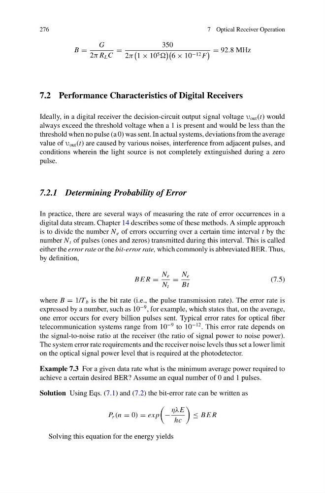
B =
G
2π R L C
=
350
2π
1 × 10 5
6 × 10 −12 F
= 92.8 MHz
7.2 Performance Characteristics of Digital Receivers
Ideally, in a digital receiver the decision-circuit output signal voltage υ out (t) would
always exceed the threshold voltage when a 1 is present and would be less than the
threshold when no pulse (a 0) was sent. In actual systems, deviations from the average
value of υ out (t) are caused by various noises, interference from adjacent pulses, and
conditions wherein the light source is not completely extinguished during a zero
pulse.
7.2.1 Determining Probability of Error
In practice, there are several ways of measuring the rate of error occurrences in a
digital data stream. Chapter 14 describes some of these methods. A simple approach
is to divide the number N e of errors occurring over a certain time interval t by the
number N t of pulses (ones and zeros) transmitted during this interval. This is called
either the error rate or the bit-error rate, which commonly is abbreviated BER. Thus,
by definition,
B E R =
N e
N t
=
N e
Bt
(7.5)
where B = 1/T b is the bit rate (i.e., the pulse transmission rate). The error rate is
expressed by a number, such as 10
−9 , for example, which states that, on the average,
one error occurs for every billion pulses sent. Typical error rates for optical fiber
telecommunication systems range from 10
−9 to 10
−12 . This error rate depends on
the signal-to-noise ratio at the receiver (the ratio of signal power to noise power).
The system error rate requirements and the receiver noise levels thus set a lower limit
on the optical signal power level that is required at the photodetector.
Example 7.3 For a given data rate what is the minimum average power required to
achieve a certain desired BER? Assume an equal number of 0 and 1 pulses.
Solution Using Eqs. (7.1) and (7.2) the bit-error rate can be written as
P r (n = 0) = ex p
−
ηλE
hc
≤ B E R
Solving this equation for the energy yields
7 Optical Receiver Operation
B =
G
2π R L C
=
350
2π
1 × 10 5
6 × 10 −12 F
= 92.8 MHz
7.2 Performance Characteristics of Digital Receivers
Ideally, in a digital receiver the decision-circuit output signal voltage υ out (t) would
always exceed the threshold voltage when a 1 is present and would be less than the
threshold when no pulse (a 0) was sent. In actual systems, deviations from the average
value of υ out (t) are caused by various noises, interference from adjacent pulses, and
conditions wherein the light source is not completely extinguished during a zero
pulse.
7.2.1 Determining Probability of Error
In practice, there are several ways of measuring the rate of error occurrences in a
digital data stream. Chapter 14 describes some of these methods. A simple approach
is to divide the number N e of errors occurring over a certain time interval t by the
number N t of pulses (ones and zeros) transmitted during this interval. This is called
either the error rate or the bit-error rate, which commonly is abbreviated BER. Thus,
by definition,
B E R =
N e
N t
=
N e
Bt
(7.5)
where B = 1/T b is the bit rate (i.e., the pulse transmission rate). The error rate is
expressed by a number, such as 10
−9 , for example, which states that, on the average,
one error occurs for every billion pulses sent. Typical error rates for optical fiber
telecommunication systems range from 10
−9 to 10
−12 . This error rate depends on
the signal-to-noise ratio at the receiver (the ratio of signal power to noise power).
The system error rate requirements and the receiver noise levels thus set a lower limit
on the optical signal power level that is required at the photodetector.
Example 7.3 For a given data rate what is the minimum average power required to
achieve a certain desired BER? Assume an equal number of 0 and 1 pulses.
Solution Using Eqs. (7.1) and (7.2) the bit-error rate can be written as
P r (n = 0) = ex p
−
ηλE
hc
≤ B E R
Solving this equation for the energy yields