

274
7 Optical Receiver Operation
7.1.3 Receiver Front-End Amplifiers
Noise sources at the front end of a receiver dominate the sensitivity and bandwidth, so
a major engineering emphasis has been on the design of a low-noise front-end amplifier. The goals generally are to maximize the receiver sensitivity while maintaining
a suitable bandwidth. To achieve these goals, a basic concern in front-end design is
what load resistor R L to choose because this parameter affects both the bandwidth
and the noise performance. Front-end amplifiers used in optical fiber communication
systems can be classified into three broad categories, which are the low-impedance,
the high-impedance, and the transimpedance designs. These categories are not actually distinct because a continuum of intermediate configurations is possible, but they
serve to illustrate the design approaches.
The low-impedance (LZ) preamplifier is the most straightforward configuration,
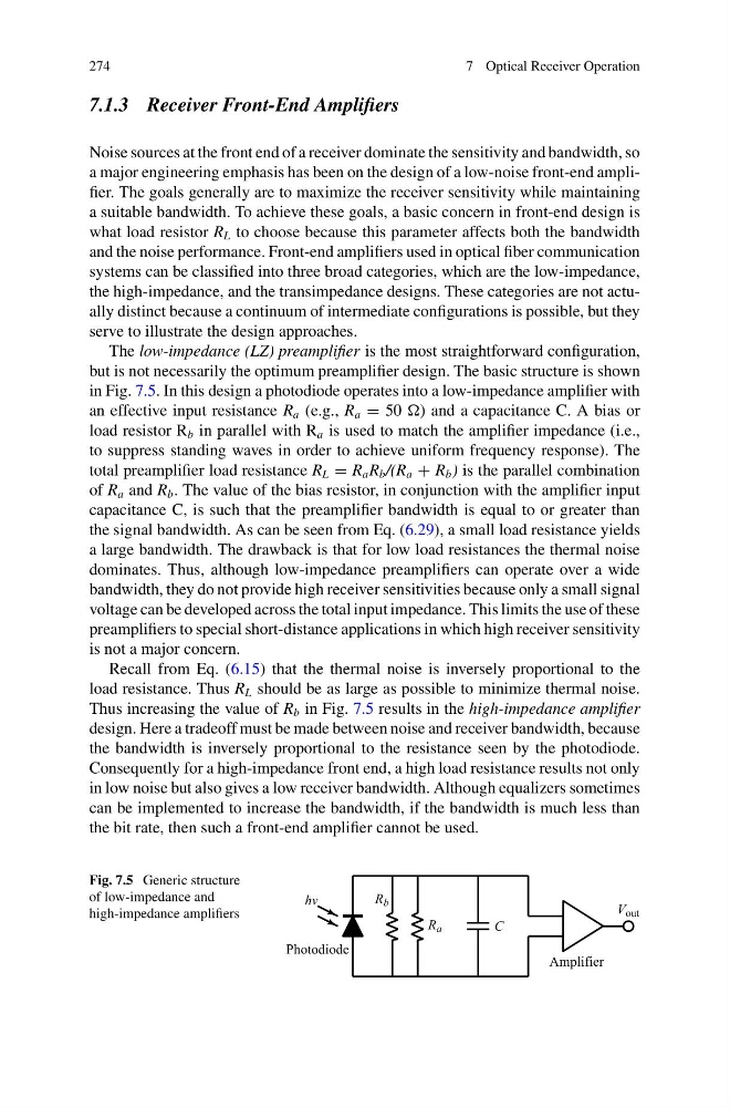
but is not necessarily the optimum preamplifier design. The basic structure is shown
in Fig. 7.5. In this design a photodiode operates into a low-impedance amplifier with
an effective input resistance R a (e.g., R a = 50 ) and a capacitance C. A bias or
load resistor R b in parallel with R a is used to match the amplifier impedance (i.e.,
to suppress standing waves in order to achieve uniform frequency response). The
total preamplifier load resistance R L = R a R b /(R a + R b ) is the parallel combination
of R a and R b . The value of the bias resistor, in conjunction with the amplifier input
capacitance C, is such that the preamplifier bandwidth is equal to or greater than
the signal bandwidth. As can be seen from Eq. (6.29), a small load resistance yields
a large bandwidth. The drawback is that for low load resistances the thermal noise
dominates. Thus, although low-impedance preamplifiers can operate over a wide
bandwidth, they do not provide high receiver sensitivities because only a small signal
voltage can be developed across the total input impedance. This limits the use of these
preamplifiers to special short-distance applications in which high receiver sensitivity
is not a major concern.
Recall from Eq. (6.15) that the thermal noise is inversely proportional to the
load resistance. Thus R L should be as large as possible to minimize thermal noise.
Thus increasing the value of R b in Fig. 7.5 results in the high-impedance amplifier
design. Here a tradeoff must be made between noise and receiver bandwidth, because
the bandwidth is inversely proportional to the resistance seen by the photodiode.
Consequently for a high-impedance front end, a high load resistance results not only
in low noise but also gives a low receiver bandwidth. Although equalizers sometimes
can be implemented to increase the bandwidth, if the bandwidth is much less than
the bit rate, then such a front-end amplifier cannot be used.
Fig. 7.5 Generic structure
of low-impedance and
high-impedance amplifiers
7 Optical Receiver Operation
7.1.3 Receiver Front-End Amplifiers
Noise sources at the front end of a receiver dominate the sensitivity and bandwidth, so
a major engineering emphasis has been on the design of a low-noise front-end amplifier. The goals generally are to maximize the receiver sensitivity while maintaining
a suitable bandwidth. To achieve these goals, a basic concern in front-end design is
what load resistor R L to choose because this parameter affects both the bandwidth
and the noise performance. Front-end amplifiers used in optical fiber communication
systems can be classified into three broad categories, which are the low-impedance,
the high-impedance, and the transimpedance designs. These categories are not actually distinct because a continuum of intermediate configurations is possible, but they
serve to illustrate the design approaches.
The low-impedance (LZ) preamplifier is the most straightforward configuration,
but is not necessarily the optimum preamplifier design. The basic structure is shown
in Fig. 7.5. In this design a photodiode operates into a low-impedance amplifier with
an effective input resistance R a (e.g., R a = 50 ) and a capacitance C. A bias or
load resistor R b in parallel with R a is used to match the amplifier impedance (i.e.,
to suppress standing waves in order to achieve uniform frequency response). The
total preamplifier load resistance R L = R a R b /(R a + R b ) is the parallel combination
of R a and R b . The value of the bias resistor, in conjunction with the amplifier input
capacitance C, is such that the preamplifier bandwidth is equal to or greater than
the signal bandwidth. As can be seen from Eq. (6.29), a small load resistance yields
a large bandwidth. The drawback is that for low load resistances the thermal noise
dominates. Thus, although low-impedance preamplifiers can operate over a wide
bandwidth, they do not provide high receiver sensitivities because only a small signal
voltage can be developed across the total input impedance. This limits the use of these
preamplifiers to special short-distance applications in which high receiver sensitivity
is not a major concern.
Recall from Eq. (6.15) that the thermal noise is inversely proportional to the
load resistance. Thus R L should be as large as possible to minimize thermal noise.
Thus increasing the value of R b in Fig. 7.5 results in the high-impedance amplifier
design. Here a tradeoff must be made between noise and receiver bandwidth, because
the bandwidth is inversely proportional to the resistance seen by the photodiode.
Consequently for a high-impedance front end, a high load resistance results not only
in low noise but also gives a low receiver bandwidth. Although equalizers sometimes
can be implemented to increase the bandwidth, if the bandwidth is much less than
the bit rate, then such a front-end amplifier cannot be used.
Fig. 7.5 Generic structure
of low-impedance and
high-impedance amplifiers