

7.1 Basic Receiver Operation
273
E ≥ (12 ln10)
hc
ηλ
= 42.5
hc
ηλ
is required in a 1 pulse to have a probability of 10
−12 or smaller in order
that the arriving 1 pulse will not be interpreted as a 0 pulse. (b) Why must the
number of photons in the 1 pulse be greater than or equal to 66?
The fact that it is not possible to predict exactly how many electron–hole pairs are
generated by a known optical power incident on the detector is the origin of the excess
noise factor F(M) resulting from the random nature of the avalanche multiplication
process. Recall from Sect. 6.4 that, for an avalanche detector with a mean gain M,
for electron injection F(M) is often approximated by the empirical equation
F(M) ≈ M
x
(7.4)
where the factor x ranges between 0 and 1.0 depending on the photodiode material.
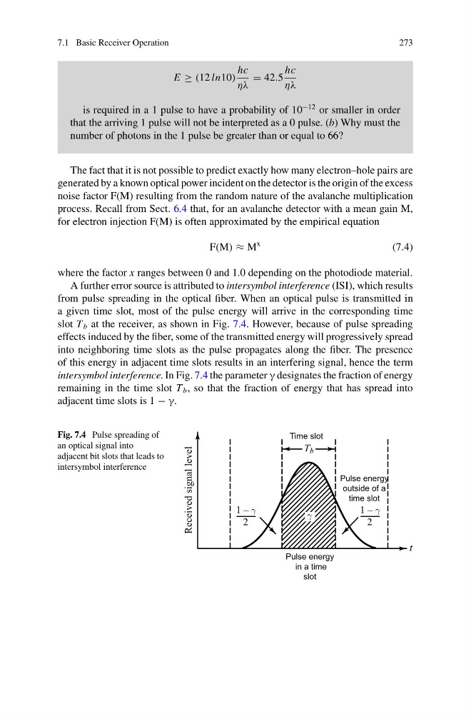
A further error source is attributed to intersymbol interference (ISI), which results
from pulse spreading in the optical fiber. When an optical pulse is transmitted in
a given time slot, most of the pulse energy will arrive in the corresponding time
slot T b at the receiver, as shown in Fig. 7.4. However, because of pulse spreading
effects induced by the fiber, some of the transmitted energy will progressively spread
into neighboring time slots as the pulse propagates along the fiber. The presence
of this energy in adjacent time slots results in an interfering signal, hence the term
intersymbol interference. In Fig. 7.4 the parameter γ designates the fraction of energy
remaining in the time slot T b , so that the fraction of energy that has spread into
adjacent time slots is 1 − γ.
Fig. 7.4 Pulse spreading of
an optical signal into
adjacent bit slots that leads to
intersymbol interference
Pulse energy
in a time
slot
Pulse energy
outside of a
time slot
Time slot
273
E ≥ (12 ln10)
hc
ηλ
= 42.5
hc
ηλ
is required in a 1 pulse to have a probability of 10
−12 or smaller in order
that the arriving 1 pulse will not be interpreted as a 0 pulse. (b) Why must the
number of photons in the 1 pulse be greater than or equal to 66?
The fact that it is not possible to predict exactly how many electron–hole pairs are
generated by a known optical power incident on the detector is the origin of the excess
noise factor F(M) resulting from the random nature of the avalanche multiplication
process. Recall from Sect. 6.4 that, for an avalanche detector with a mean gain M,
for electron injection F(M) is often approximated by the empirical equation
F(M) ≈ M
x
(7.4)
where the factor x ranges between 0 and 1.0 depending on the photodiode material.
A further error source is attributed to intersymbol interference (ISI), which results
from pulse spreading in the optical fiber. When an optical pulse is transmitted in
a given time slot, most of the pulse energy will arrive in the corresponding time
slot T b at the receiver, as shown in Fig. 7.4. However, because of pulse spreading
effects induced by the fiber, some of the transmitted energy will progressively spread
into neighboring time slots as the pulse propagates along the fiber. The presence
of this energy in adjacent time slots results in an interfering signal, hence the term
intersymbol interference. In Fig. 7.4 the parameter γ designates the fraction of energy
remaining in the time slot T b , so that the fraction of energy that has spread into
adjacent time slots is 1 − γ.
Fig. 7.4 Pulse spreading of
an optical signal into
adjacent bit slots that leads to
intersymbol interference
Pulse energy
in a time
slot
Pulse energy
outside of a
time slot
Time slot