

270
7 Optical Receiver Operation
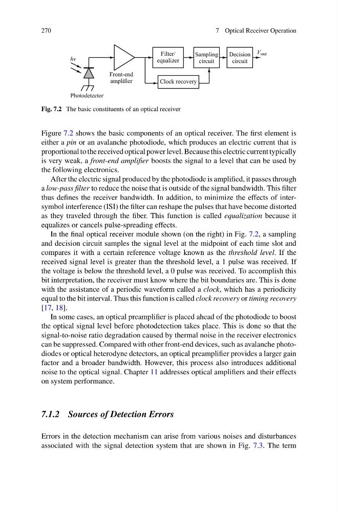
Fig. 7.2 The basic constituents of an optical receiver
Figure 7.2 shows the basic components of an optical receiver. The first element is
either a pin or an avalanche photodiode, which produces an electric current that is
proportional to the received optical power level. Because this electric current typically
is very weak, a front-end amplifier boosts the signal to a level that can be used by
the following electronics.
After the electric signal produced by the photodiode is amplified, it passes through
a low-pass filter to reduce the noise that is outside of the signal bandwidth. This filter
thus defines the receiver bandwidth. In addition, to minimize the effects of intersymbol interference (ISI) the filter can reshape the pulses that have become distorted
as they traveled through the fiber. This function is called equalization because it
equalizes or cancels pulse-spreading effects.
In the final optical receiver module shown (on the right) in Fig. 7.2, a sampling
and decision circuit samples the signal level at the midpoint of each time slot and
compares it with a certain reference voltage known as the threshold level. If the
received signal level is greater than the threshold level, a 1 pulse was received. If
the voltage is below the threshold level, a 0 pulse was received. To accomplish this
bit interpretation, the receiver must know where the bit boundaries are. This is done
with the assistance of a periodic waveform called a clock, which has a periodicity
equal to the bit interval. Thus this function is called clock recovery or timing recovery
[17, 18].
In some cases, an optical preamplifier is placed ahead of the photodiode to boost
the optical signal level before photodetection takes place. This is done so that the
signal-to-noise ratio degradation caused by thermal noise in the receiver electronics
can be suppressed. Compared with other front-end devices, such as avalanche photodiodes or optical heterodyne detectors, an optical preamplifier provides a larger gain
factor and a broader bandwidth. However, this process also introduces additional
noise to the optical signal. Chapter 11 addresses optical amplifiers and their effects
on system performance.
7.1.2 Sources of Detection Errors
Errors in the detection mechanism can arise from various noises and disturbances
associated with the signal detection system that are shown in Fig. 7.3. The term
7 Optical Receiver Operation
Fig. 7.2 The basic constituents of an optical receiver
Figure 7.2 shows the basic components of an optical receiver. The first element is
either a pin or an avalanche photodiode, which produces an electric current that is
proportional to the received optical power level. Because this electric current typically
is very weak, a front-end amplifier boosts the signal to a level that can be used by
the following electronics.
After the electric signal produced by the photodiode is amplified, it passes through
a low-pass filter to reduce the noise that is outside of the signal bandwidth. This filter
thus defines the receiver bandwidth. In addition, to minimize the effects of intersymbol interference (ISI) the filter can reshape the pulses that have become distorted
as they traveled through the fiber. This function is called equalization because it
equalizes or cancels pulse-spreading effects.
In the final optical receiver module shown (on the right) in Fig. 7.2, a sampling
and decision circuit samples the signal level at the midpoint of each time slot and
compares it with a certain reference voltage known as the threshold level. If the
received signal level is greater than the threshold level, a 1 pulse was received. If
the voltage is below the threshold level, a 0 pulse was received. To accomplish this
bit interpretation, the receiver must know where the bit boundaries are. This is done
with the assistance of a periodic waveform called a clock, which has a periodicity
equal to the bit interval. Thus this function is called clock recovery or timing recovery
[17, 18].
In some cases, an optical preamplifier is placed ahead of the photodiode to boost
the optical signal level before photodetection takes place. This is done so that the
signal-to-noise ratio degradation caused by thermal noise in the receiver electronics
can be suppressed. Compared with other front-end devices, such as avalanche photodiodes or optical heterodyne detectors, an optical preamplifier provides a larger gain
factor and a broader bandwidth. However, this process also introduces additional
noise to the optical signal. Chapter 11 addresses optical amplifiers and their effects
on system performance.
7.1.2 Sources of Detection Errors
Errors in the detection mechanism can arise from various noises and disturbances
associated with the signal detection system that are shown in Fig. 7.3. The term