

7.1 Basic Receiver Operation
269
7.1.1 Transmitting Digital Signals
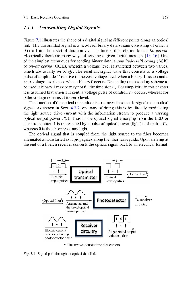
Figure 7.1 illustrates the shape of a digital signal at different points along an optical
link. The transmitted signal is a two-level binary data stream consisting of either a
0 or a 1 in a time slot of duration T b . This time slot is referred to as a bit period.
Electrically there are many ways of sending a given digital message [13–16]. One
of the simplest techniques for sending binary data is amplitude-shift keying (ASK)
or on–off keying (OOK), wherein a voltage level is switched between two values,
which are usually on or off . The resultant signal wave thus consists of a voltage
pulse of amplitude V relative to the zero voltage level when a binary 1 occurs and a
zero-voltage-level space when a binary 0 occurs. Depending on the coding scheme to
be used, a binary 1 may or may not fill the time slot T b . For simplicity, in this chapter
it is assumed that when 1 is sent, a voltage pulse of duration T b occurs, whereas for
0 the voltage remains at its zero level.
The function of the optical transmitter is to convert the electric signal to an optical
signal. As shown in Sect. 4.3.7, one way of doing this is by directly modulating
the light source drive current with the information stream to produce a varying
optical output power P(t). Thus in the optical signal emerging from the LED or
laser transmitter, 1 is represented by a pulse of optical power (light) of duration T b ,
whereas 0 is the absence of any light.
The optical signal that is coupled from the light source to the fiber becomes
attenuated and distorted as it propagates along the fiber waveguide. Upon arriving at
the end of a fiber, a receiver converts the optical signal back to an electrical format.
Optical
transmitter
Photodetector
Receiver
circuitry
To receiver
circuitry
The arrows denote time slot centers
Fig. 7.1 Signal path through an optical data link
269
7.1.1 Transmitting Digital Signals
Figure 7.1 illustrates the shape of a digital signal at different points along an optical
link. The transmitted signal is a two-level binary data stream consisting of either a
0 or a 1 in a time slot of duration T b . This time slot is referred to as a bit period.
Electrically there are many ways of sending a given digital message [13–16]. One
of the simplest techniques for sending binary data is amplitude-shift keying (ASK)
or on–off keying (OOK), wherein a voltage level is switched between two values,
which are usually on or off . The resultant signal wave thus consists of a voltage
pulse of amplitude V relative to the zero voltage level when a binary 1 occurs and a
zero-voltage-level space when a binary 0 occurs. Depending on the coding scheme to
be used, a binary 1 may or may not fill the time slot T b . For simplicity, in this chapter
it is assumed that when 1 is sent, a voltage pulse of duration T b occurs, whereas for
0 the voltage remains at its zero level.
The function of the optical transmitter is to convert the electric signal to an optical
signal. As shown in Sect. 4.3.7, one way of doing this is by directly modulating
the light source drive current with the information stream to produce a varying
optical output power P(t). Thus in the optical signal emerging from the LED or
laser transmitter, 1 is represented by a pulse of optical power (light) of duration T b ,
whereas 0 is the absence of any light.
The optical signal that is coupled from the light source to the fiber becomes
attenuated and distorted as it propagates along the fiber waveguide. Upon arriving at
the end of a fiber, a receiver converts the optical signal back to an electrical format.
Optical
transmitter
Photodetector
Receiver
circuitry
To receiver
circuitry
The arrows denote time slot centers
Fig. 7.1 Signal path through an optical data link