

262
6 Photodetection Devices
If R T is the combination of the load and amplifier input resistances and C T is the
sum of the photodiode and amplifier capacitances, as shown in Fig. 6.6, the detector
behaves approximately like a simple RC low-pass filter with a passband B c given by
B c =
1
2π R T C T
(6.31)
Example 6.12 If the photodiode capacitance is 3 pF, the amplifier capacitance is 4
pF, the load resistor is 1 k, and the amplifier input resistance is 1 M, then C T =
7 pF and R T = 1 k, so that the circuit bandwidth is.
B c =
1
2π R T C T
= 23 MHz
If the photodector load resistance is reduced to 50 , then the circuit bandwidth
becomes B c = 455 MHz.
6.4 Comparisons of Photodetectors
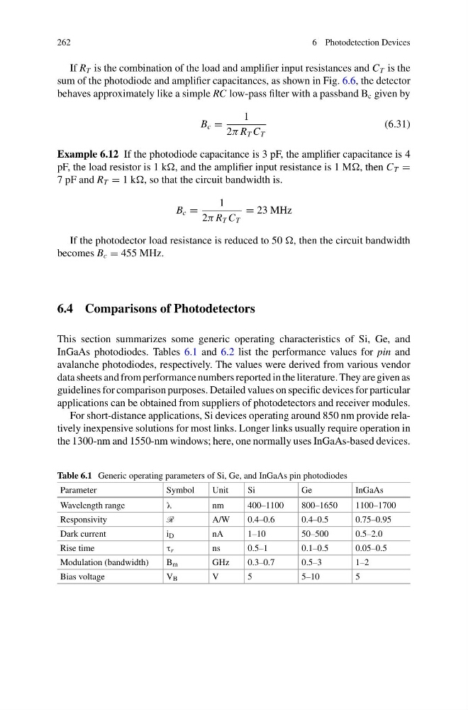
This section summarizes some generic operating characteristics of Si, Ge, and
InGaAs photodiodes. Tables 6.1 and 6.2 list the performance values for pin and
avalanche photodiodes, respectively. The values were derived from various vendor
data sheets and from performance numbers reported in the literature. They are given as
guidelines for comparison purposes. Detailed values on specific devices for particular
applications can be obtained from suppliers of photodetectors and receiver modules.
For short-distance applications, Si devices operating around 850 nm provide relatively inexpensive solutions for most links. Longer links usually require operation in
the 1300-nm and 1550-nm windows; here, one normally uses InGaAs-based devices.
Table 6.1 Generic operating parameters of Si, Ge, and InGaAs pin photodiodes
Parameter
Symbol
Unit
Si
Ge
InGaAs
Wavelength range
λ
nm
400–1100
800–1650
1100–1700
Responsivity
R
A/W
0.4–0.6
0.4–0.5
0.75–0.95
Dark current
i D
nA
1–10
50–500
0.5–2.0
Rise time
τ r
ns
0.5–1
0.1–0.5
0.05–0.5
Modulation (bandwidth)
B m
GHz
0.3–0.7
0.5–3
1–2
Bias voltage
V B
V
5
5–10
5
6 Photodetection Devices
If R T is the combination of the load and amplifier input resistances and C T is the
sum of the photodiode and amplifier capacitances, as shown in Fig. 6.6, the detector
behaves approximately like a simple RC low-pass filter with a passband B c given by
B c =
1
2π R T C T
(6.31)
Example 6.12 If the photodiode capacitance is 3 pF, the amplifier capacitance is 4
pF, the load resistor is 1 k, and the amplifier input resistance is 1 M, then C T =
7 pF and R T = 1 k, so that the circuit bandwidth is.
B c =
1
2π R T C T
= 23 MHz
If the photodector load resistance is reduced to 50 , then the circuit bandwidth
becomes B c = 455 MHz.
6.4 Comparisons of Photodetectors
This section summarizes some generic operating characteristics of Si, Ge, and
InGaAs photodiodes. Tables 6.1 and 6.2 list the performance values for pin and
avalanche photodiodes, respectively. The values were derived from various vendor
data sheets and from performance numbers reported in the literature. They are given as
guidelines for comparison purposes. Detailed values on specific devices for particular
applications can be obtained from suppliers of photodetectors and receiver modules.
For short-distance applications, Si devices operating around 850 nm provide relatively inexpensive solutions for most links. Longer links usually require operation in
the 1300-nm and 1550-nm windows; here, one normally uses InGaAs-based devices.
Table 6.1 Generic operating parameters of Si, Ge, and InGaAs pin photodiodes
Parameter
Symbol
Unit
Si
Ge
InGaAs
Wavelength range
λ
nm
400–1100
800–1650
1100–1700
Responsivity
R
A/W
0.4–0.6
0.4–0.5
0.75–0.95
Dark current
i D
nA
1–10
50–500
0.5–2.0
Rise time
τ r
ns
0.5–1
0.1–0.5
0.05–0.5
Modulation (bandwidth)
B m
GHz
0.3–0.7
0.5–3
1–2
Bias voltage
V B
V
5
5–10
5