

6.2 Noise Effects in Photodetectors
251
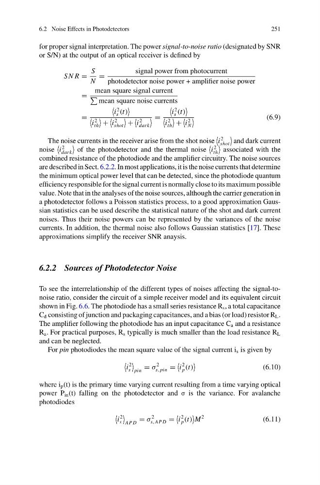
for proper signal interpretation. The power signal-to-noise ratio (designated by SNR
or S/N) at the output of an optical receiver is defined by
S N R =
S
N
=
signal power from photocurrent
photodetector noise power + amplifier noise power
=
mean square signal current
mean square noise currents
=
i
2
s (t)
i
2
th
+
i
2
shot
+
i
2
dark
=
i
2
s (t)
i
2
th
+
i
2
N
(6.9)
The noise currents in the receiver arise from the shot noise
i
2
shot
and dark current
noise
i
2
dark
of the photodetector and the thermal noise
i
2
th
associated with the
combined resistance of the photodiode and the amplifier circuitry. The noise sources
are described in Sect. 6.2.2. In most applications, it is the noise currents that determine
the minimum optical power level that can be detected, since the photodiode quantum
efficiency responsible for the signal current is normally close to its maximum possible
value. Note that in the analyses of the noise sources, although the carrier generation in
a photodetector follows a Poisson statistics process, to a good approximation Gaussian statistics can be used describe the statistical nature of the shot and dark current
noises. Thus their noise powers can be represented by the variances of the noise
currents. In addition, the thermal noise also follows Gaussian statistics [17]. These
approximations simplify the receiver SNR anaysis.
6.2.2 Sources of Photodetector Noise
To see the interrelationship of the different types of noises affecting the signal-tonoise ratio, consider the circuit of a simple receiver model and its equivalent circuit
shown in Fig. 6.6. The photodiode has a small series resistance R s , a total capacitance
C d consisting of junction and packaging capacitances, and a bias (or load) resistor R L .
The amplifier following the photodiode has an input capacitance C a and a resistance
R a . For practical purposes, R s typically is much smaller than the load resistance R L
and can be neglected.
For pin photodiodes the mean square value of the signal current i s is given by
i
2
s
pin
= σ
2
s, pin =
i
2
p (t)
(6.10)
where i p (t) is the primary time varying current resulting from a time varying optical
power P in (t) falling on the photodetector and σ is the variance. For avalanche
photodiodes
i
2
s
AP D
= σ
2
s,AP D =
i
2
p (t)
M
2
(6.11)
251
for proper signal interpretation. The power signal-to-noise ratio (designated by SNR
or S/N) at the output of an optical receiver is defined by
S N R =
S
N
=
signal power from photocurrent
photodetector noise power + amplifier noise power
=
mean square signal current
mean square noise currents
=
i
2
s (t)
i
2
th
+
i
2
shot
+
i
2
dark
=
i
2
s (t)
i
2
th
+
i
2
N
(6.9)
The noise currents in the receiver arise from the shot noise
i
2
shot
and dark current
noise
i
2
dark
of the photodetector and the thermal noise
i
2
th
associated with the
combined resistance of the photodiode and the amplifier circuitry. The noise sources
are described in Sect. 6.2.2. In most applications, it is the noise currents that determine
the minimum optical power level that can be detected, since the photodiode quantum
efficiency responsible for the signal current is normally close to its maximum possible
value. Note that in the analyses of the noise sources, although the carrier generation in
a photodetector follows a Poisson statistics process, to a good approximation Gaussian statistics can be used describe the statistical nature of the shot and dark current
noises. Thus their noise powers can be represented by the variances of the noise
currents. In addition, the thermal noise also follows Gaussian statistics [17]. These
approximations simplify the receiver SNR anaysis.
6.2.2 Sources of Photodetector Noise
To see the interrelationship of the different types of noises affecting the signal-tonoise ratio, consider the circuit of a simple receiver model and its equivalent circuit
shown in Fig. 6.6. The photodiode has a small series resistance R s , a total capacitance
C d consisting of junction and packaging capacitances, and a bias (or load) resistor R L .
The amplifier following the photodiode has an input capacitance C a and a resistance
R a . For practical purposes, R s typically is much smaller than the load resistance R L
and can be neglected.
For pin photodiodes the mean square value of the signal current i s is given by
i
2
s
pin
= σ
2
s, pin =
i
2
p (t)
(6.10)
where i p (t) is the primary time varying current resulting from a time varying optical
power P in (t) falling on the photodetector and σ is the variance. For avalanche
photodiodes
i
2
s
AP D
= σ
2
s,AP D =
i
2
p (t)
M
2
(6.11)