

212
5 Optical Power Coupling
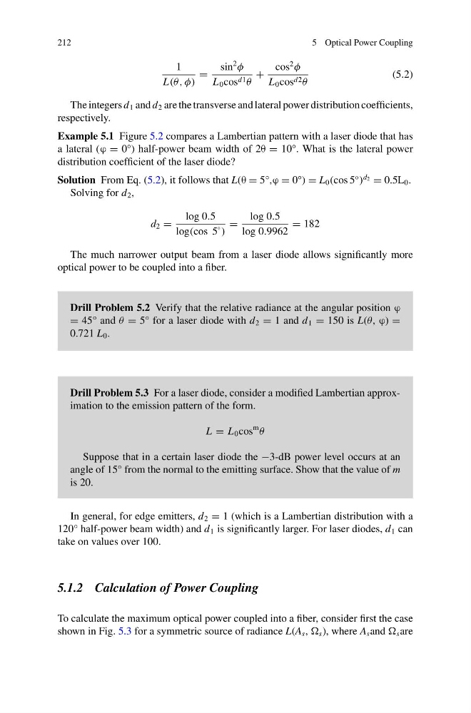
1
L(θ, φ)
=
sin
2
φ
L 0 cos d1 θ
+
cos
2
φ
L 0 cos d2 θ
(5.2)
The integers d 1 and d 2 are the transverse and lateral power distribution coefficients,
respectively.
Example 5.1 Figure 5.2 compares a Lambertian pattern with a laser diode that has
a lateral (ϕ = 0°) half-power beam width of 2θ = 10°. What is the lateral power
distribution coefficient of the laser diode?
Solution From Eq. (5.2), it follows that L(θ = 5°,ϕ = 0°) = L 0 (cos 5
◦
)
d 2 = 0.5L 0 .
Solving for d 2 ,
d 2 =
log 0.5
log(cos 5
◦ )
=
log 0.5
log 0.9962
= 182
The much narrower output beam from a laser diode allows significantly more
optical power to be coupled into a fiber.
Drill Problem 5.2 Verify that the relative radiance at the angular position ϕ
= 45° and θ = 5° for a laser diode with d 2 = 1 and d 1 = 150 is L(θ, ϕ) =
0.721 L 0 .
Drill Problem 5.3 For a laser diode, consider a modified Lambertian approximation to the emission pattern of the form.
L = L 0 cos
m
θ
Suppose that in a certain laser diode the −3-dB power level occurs at an
angle of 15° from the normal to the emitting surface. Show that the value of m
is 20.
In general, for edge emitters, d 2 = 1 (which is a Lambertian distribution with a
120° half-power beam width) and d 1 is significantly larger. For laser diodes, d 1 can
take on values over 100.
5.1.2 Calculation of Power Coupling
To calculate the maximum optical power coupled into a fiber, consider first the case
shown in Fig. 5.3 for a symmetric source of radiance L(A s , s ), where A s and s are
5 Optical Power Coupling
1
L(θ, φ)
=
sin
2
φ
L 0 cos d1 θ
+
cos
2
φ
L 0 cos d2 θ
(5.2)
The integers d 1 and d 2 are the transverse and lateral power distribution coefficients,
respectively.
Example 5.1 Figure 5.2 compares a Lambertian pattern with a laser diode that has
a lateral (ϕ = 0°) half-power beam width of 2θ = 10°. What is the lateral power
distribution coefficient of the laser diode?
Solution From Eq. (5.2), it follows that L(θ = 5°,ϕ = 0°) = L 0 (cos 5
◦
)
d 2 = 0.5L 0 .
Solving for d 2 ,
d 2 =
log 0.5
log(cos 5
◦ )
=
log 0.5
log 0.9962
= 182
The much narrower output beam from a laser diode allows significantly more
optical power to be coupled into a fiber.
Drill Problem 5.2 Verify that the relative radiance at the angular position ϕ
= 45° and θ = 5° for a laser diode with d 2 = 1 and d 1 = 150 is L(θ, ϕ) =
0.721 L 0 .
Drill Problem 5.3 For a laser diode, consider a modified Lambertian approximation to the emission pattern of the form.
L = L 0 cos
m
θ
Suppose that in a certain laser diode the −3-dB power level occurs at an
angle of 15° from the normal to the emitting surface. Show that the value of m
is 20.
In general, for edge emitters, d 2 = 1 (which is a Lambertian distribution with a
120° half-power beam width) and d 1 is significantly larger. For laser diodes, d 1 can
take on values over 100.
5.1.2 Calculation of Power Coupling
To calculate the maximum optical power coupled into a fiber, consider first the case
shown in Fig. 5.3 for a symmetric source of radiance L(A s , s ), where A s and s are