

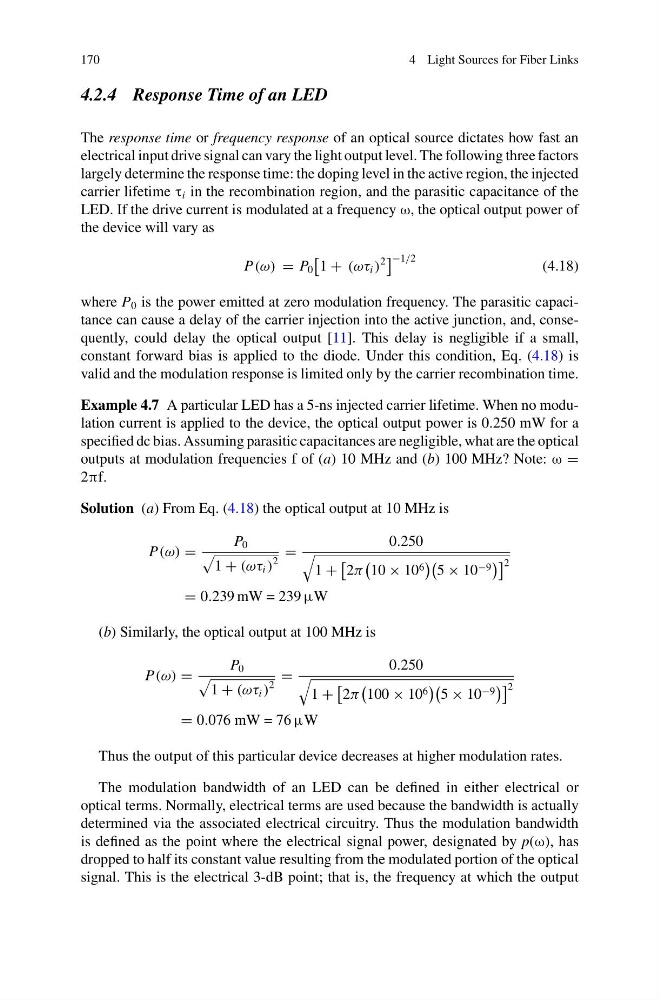
170
4 Light Sources for Fiber Links
4.2.4 Response Time of an LED
The response time or frequency response of an optical source dictates how fast an
electrical input drive signal can vary the light output level. The following three factors
largely determine the response time: the doping level in the active region, the injected
carrier lifetime τ i in the recombination region, and the parasitic capacitance of the
LED. If the drive current is modulated at a frequency ω, the optical output power of
the device will vary as
P(ω) = P 0
1 + (ωτ i )
2
−1/2
(4.18)
where P 0 is the power emitted at zero modulation frequency. The parasitic capacitance can cause a delay of the carrier injection into the active junction, and, consequently, could delay the optical output [11]. This delay is negligible if a small,
constant forward bias is applied to the diode. Under this condition, Eq. (4.18) is
valid and the modulation response is limited only by the carrier recombination time.
Example 4.7 A particular LED has a 5-ns injected carrier lifetime. When no modulation current is applied to the device, the optical output power is 0.250 mW for a
specified dc bias. Assuming parasitic capacitances are negligible, what are the optical
outputs at modulation frequencies f of (a) 10 MHz and (b) 100 MHz? Note: ω =
2πf.
Solution (a) From Eq. (4.18) the optical output at 10 MHz is
P(ω) =
P 0
1 + (ωτ i )
2
=
0.250
1 +
2π
10 × 10 6
5 × 10 −9
2
= 0.239 mW = 239 μW
(b) Similarly, the optical output at 100 MHz is
P(ω) =
P 0
1 + (ωτ i )
2
=
0.250
1 +
2π
100 × 10 6
5 × 10 −9
2
= 0.076 mW = 76 μW
Thus the output of this particular device decreases at higher modulation rates.
The modulation bandwidth of an LED can be defined in either electrical or
optical terms. Normally, electrical terms are used because the bandwidth is actually
determined via the associated electrical circuitry. Thus the modulation bandwidth
is defined as the point where the electrical signal power, designated by p(ω), has
dropped to half its constant value resulting from the modulated portion of the optical
signal. This is the electrical 3-dB point; that is, the frequency at which the output
4 Light Sources for Fiber Links
4.2.4 Response Time of an LED
The response time or frequency response of an optical source dictates how fast an
electrical input drive signal can vary the light output level. The following three factors
largely determine the response time: the doping level in the active region, the injected
carrier lifetime τ i in the recombination region, and the parasitic capacitance of the
LED. If the drive current is modulated at a frequency ω, the optical output power of
the device will vary as
P(ω) = P 0
1 + (ωτ i )
2
−1/2
(4.18)
where P 0 is the power emitted at zero modulation frequency. The parasitic capacitance can cause a delay of the carrier injection into the active junction, and, consequently, could delay the optical output [11]. This delay is negligible if a small,
constant forward bias is applied to the diode. Under this condition, Eq. (4.18) is
valid and the modulation response is limited only by the carrier recombination time.
Example 4.7 A particular LED has a 5-ns injected carrier lifetime. When no modulation current is applied to the device, the optical output power is 0.250 mW for a
specified dc bias. Assuming parasitic capacitances are negligible, what are the optical
outputs at modulation frequencies f of (a) 10 MHz and (b) 100 MHz? Note: ω =
2πf.
Solution (a) From Eq. (4.18) the optical output at 10 MHz is
P(ω) =
P 0
1 + (ωτ i )
2
=
0.250
1 +
2π
10 × 10 6
5 × 10 −9
2
= 0.239 mW = 239 μW
(b) Similarly, the optical output at 100 MHz is
P(ω) =
P 0
1 + (ωτ i )
2
=
0.250
1 +
2π
100 × 10 6
5 × 10 −9
2
= 0.076 mW = 76 μW
Thus the output of this particular device decreases at higher modulation rates.
The modulation bandwidth of an LED can be defined in either electrical or
optical terms. Normally, electrical terms are used because the bandwidth is actually
determined via the associated electrical circuitry. Thus the modulation bandwidth
is defined as the point where the electrical signal power, designated by p(ω), has
dropped to half its constant value resulting from the modulated portion of the optical
signal. This is the electrical 3-dB point; that is, the frequency at which the output