

160
4 Light Sources for Fiber Links
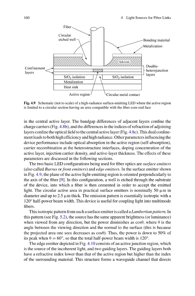
Fig. 4.9 Schematic (not to scale) of a high-radiance surface-emitting LED where the active region
is limited to a circular section having an area compatible with the fiber-core end face
in the central active layer. The bandgap differences of adjacent layers confine the
charge carriers (Fig. 4.8b), and the differences in the indices of refraction of adjoining
layers confine the optical field to the central active layer (Fig. 4.8c). This dual confinement leads to both high efficiency and high radiance. Other parameters influencing the
device performance include optical absorption in the active region (self-absorption),
carrier recombination at the heterostructure interfaces, doping concentration of the
active layer, injection carrier density, and active-layer thickness. The effects of these
parameters are discussed in the following sections.
The two basic LED configurations being used for fiber optics are surface emitters
(also called Burrus or front emitters) and edge emitters. In the surface emitter shown
in Fig. 4.9, the plane of the active light-emitting region is oriented perpendicularly to
the axis of the fiber [9]. In this configuration, a well is etched through the substrate
of the device, into which a fiber is then cemented in order to accept the emitted
light. The circular active area in practical surface emitters is nominally 50 μm in
diameter and up to 2.5 μm thick. The emission pattern is essentially isotropic with a
120° half-power beam width. This device is useful for coupling light into multimode
fibers.
This isotropic pattern from such a surface emitter is called a Lambertian pattern. In
this pattern (see Fig. 5.2), the source has the same apparent brightness (or luminance)
when viewed from any direction, but the power diminishes as cosθ, where θ is the
angle between the viewing direction and the normal to the surface (this is because
the projected area one sees decreases as cosθ). Thus, the power is down to 50% of
its peak when θ = 60°, so that the total half-power beam width is 120°.
The edge emitter depicted in Fig. 4.10 consists of an active junction region, which
is the source of the incoherent light, and two guiding layers. The guiding layers both
have a refractive index lower than that of the active region but higher than the index
of the surrounding material. This structure forms a waveguide channel that directs
4 Light Sources for Fiber Links
Fig. 4.9 Schematic (not to scale) of a high-radiance surface-emitting LED where the active region
is limited to a circular section having an area compatible with the fiber-core end face
in the central active layer. The bandgap differences of adjacent layers confine the
charge carriers (Fig. 4.8b), and the differences in the indices of refraction of adjoining
layers confine the optical field to the central active layer (Fig. 4.8c). This dual confinement leads to both high efficiency and high radiance. Other parameters influencing the
device performance include optical absorption in the active region (self-absorption),
carrier recombination at the heterostructure interfaces, doping concentration of the
active layer, injection carrier density, and active-layer thickness. The effects of these
parameters are discussed in the following sections.
The two basic LED configurations being used for fiber optics are surface emitters
(also called Burrus or front emitters) and edge emitters. In the surface emitter shown
in Fig. 4.9, the plane of the active light-emitting region is oriented perpendicularly to
the axis of the fiber [9]. In this configuration, a well is etched through the substrate
of the device, into which a fiber is then cemented in order to accept the emitted
light. The circular active area in practical surface emitters is nominally 50 μm in
diameter and up to 2.5 μm thick. The emission pattern is essentially isotropic with a
120° half-power beam width. This device is useful for coupling light into multimode
fibers.
This isotropic pattern from such a surface emitter is called a Lambertian pattern. In
this pattern (see Fig. 5.2), the source has the same apparent brightness (or luminance)
when viewed from any direction, but the power diminishes as cosθ, where θ is the
angle between the viewing direction and the normal to the surface (this is because
the projected area one sees decreases as cosθ). Thus, the power is down to 50% of
its peak when θ = 60°, so that the total half-power beam width is 120°.
The edge emitter depicted in Fig. 4.10 consists of an active junction region, which
is the source of the incoherent light, and two guiding layers. The guiding layers both
have a refractive index lower than that of the active region but higher than the index
of the surrounding material. This structure forms a waveguide channel that directs