

3.5 Designs and Use of Specialty Fibers
139
Cladding
Stress applying
elements
Core
Core
PANDA structure
Bowtie structure
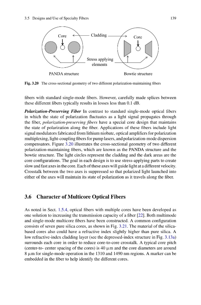
Fig. 3.20 The cross-sectional geometry of two different polarization-maintaining fibers
fibers with standard single-mode fibers. However, carefully made splices between
these different fibers typically results in losses less than 0.1 dB.
Polarization-Preserving Fiber In contrast to standard single-mode optical fibers
in which the state of polarization fluctuates as a light signal propagates through
the fiber, polarization-preserving fibers have a special core design that maintains
the state of polarization along the fiber. Applications of these fibers include light
signal modulators fabricated from lithium niobate, optical amplifiers for polarization
multiplexing, light-coupling fibers for pump lasers, and polarization-mode dispersion
compensators. Figure 3.20 illustrates the cross-sectional geometry of two different
polarization-maintaining fibers, which are known as the PANDA structure and the
bowtie structure. The light circles represent the cladding and the dark areas are the
core configurations. The goal in each design is to use stress-applying parts to create
slow and fast axes in the core. Each of these axes will guide light at a different velocity.
Crosstalk between the two axes is suppressed so that polarized light launched into
either of the axes will maintain its state of polarization as it travels along the fiber.
3.6 Character of Multicore Optical Fibers
As noted in Sect. 1.5.4, optical fibers with multiple cores have been developed as
one solution to increasing the transmission capacity of a fiber [22]. Both multimode
and single-mode multicore fibers have been constructed. A common configuration
consists of seven pure silica cores, as shown in Fig. 3.21. The material of the silicabased cores also could have a refractive index slightly higher than pure silica. A
low refractive-index cladding layer (see the depressed-index structure in Fig. 3.13a)
surrounds each core in order to reduce core-to-core crosstalk. A typical core pitch
(center-to- center spacing of the cores) is 40 μm and the core diameters are around
8 μm for single-mode operation in the 1310 and 1490 nm regions. A marker can be
embedded in the fiber to help identify the different cores.
139
Cladding
Stress applying
elements
Core
Core
PANDA structure
Bowtie structure
Fig. 3.20 The cross-sectional geometry of two different polarization-maintaining fibers
fibers with standard single-mode fibers. However, carefully made splices between
these different fibers typically results in losses less than 0.1 dB.
Polarization-Preserving Fiber In contrast to standard single-mode optical fibers
in which the state of polarization fluctuates as a light signal propagates through
the fiber, polarization-preserving fibers have a special core design that maintains
the state of polarization along the fiber. Applications of these fibers include light
signal modulators fabricated from lithium niobate, optical amplifiers for polarization
multiplexing, light-coupling fibers for pump lasers, and polarization-mode dispersion
compensators. Figure 3.20 illustrates the cross-sectional geometry of two different
polarization-maintaining fibers, which are known as the PANDA structure and the
bowtie structure. The light circles represent the cladding and the dark areas are the
core configurations. The goal in each design is to use stress-applying parts to create
slow and fast axes in the core. Each of these axes will guide light at a different velocity.
Crosstalk between the two axes is suppressed so that polarized light launched into
either of the axes will maintain its state of polarization as it travels along the fiber.
3.6 Character of Multicore Optical Fibers
As noted in Sect. 1.5.4, optical fibers with multiple cores have been developed as
one solution to increasing the transmission capacity of a fiber [22]. Both multimode
and single-mode multicore fibers have been constructed. A common configuration
consists of seven pure silica cores, as shown in Fig. 3.21. The material of the silicabased cores also could have a refractive index slightly higher than pure silica. A
low refractive-index cladding layer (see the depressed-index structure in Fig. 3.13a)
surrounds each core in order to reduce core-to-core crosstalk. A typical core pitch
(center-to- center spacing of the cores) is 40 μm and the core diameters are around
8 μm for single-mode operation in the 1310 and 1490 nm regions. A marker can be
embedded in the fiber to help identify the different cores.