

7 Development of Low Carbon Technology in China’s Iron …
257
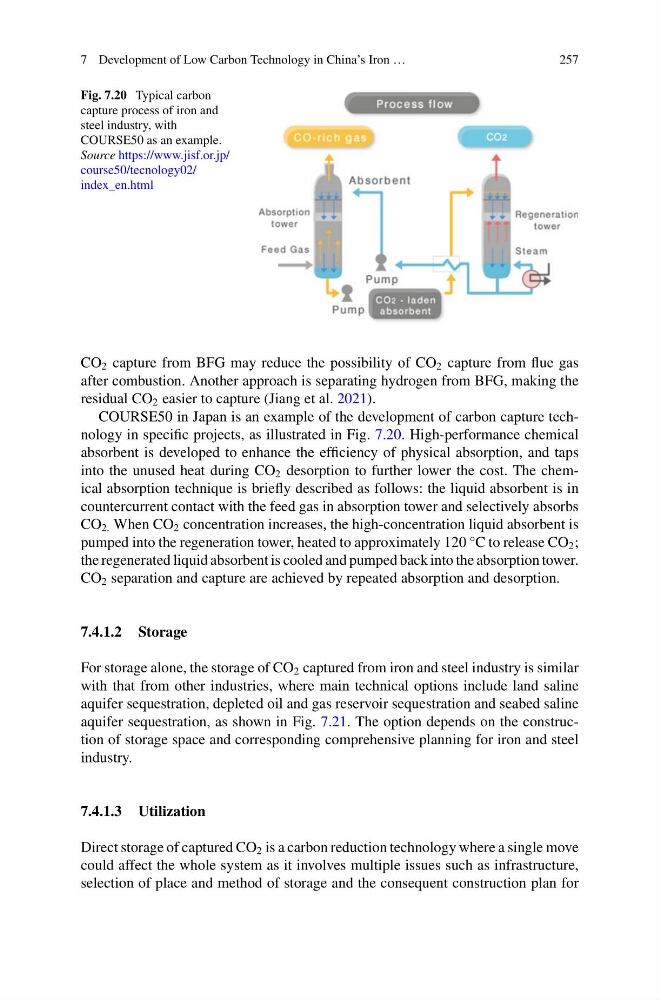
Fig. 7.20 Typical carbon
capture process of iron and
steel industry, with
COURSE50 as an example.
Source https://www.jisf.or.jp/
course50/tecnology02/
index_en.html
CO 2 capture from BFG may reduce the possibility of CO 2 capture from flue gas
after combustion. Another approach is separating hydrogen from BFG, making the
residual CO 2 easier to capture (Jiang et al. 2021).
COURSE50 in Japan is an example of the development of carbon capture technology in specific projects, as illustrated in Fig. 7.20. High-performance chemical
absorbent is developed to enhance the efficiency of physical absorption, and taps
into the unused heat during CO 2 desorption to further lower the cost. The chemical absorption technique is briefly described as follows: the liquid absorbent is in
countercurrent contact with the feed gas in absorption tower and selectively absorbs
CO 2. When CO 2 concentration increases, the high-concentration liquid absorbent is
pumped into the regeneration tower, heated to approximately 120 °C to release CO 2 ;
the regenerated liquid absorbent is cooled and pumped back into the absorption tower.
CO 2 separation and capture are achieved by repeated absorption and desorption.
7.4.1.2 Storage
For storage alone, the storage of CO 2 captured from iron and steel industry is similar
with that from other industries, where main technical options include land saline
aquifer sequestration, depleted oil and gas reservoir sequestration and seabed saline
aquifer sequestration, as shown in Fig. 7.21. The option depends on the construction of storage space and corresponding comprehensive planning for iron and steel
industry.
7.4.1.3 Utilization
Direct storage of captured CO 2 is a carbon reduction technology where a single move
could affect the whole system as it involves multiple issues such as infrastructure,
selection of place and method of storage and the consequent construction plan for
257
Fig. 7.20 Typical carbon
capture process of iron and
steel industry, with
COURSE50 as an example.
Source https://www.jisf.or.jp/
course50/tecnology02/
index_en.html
CO 2 capture from BFG may reduce the possibility of CO 2 capture from flue gas
after combustion. Another approach is separating hydrogen from BFG, making the
residual CO 2 easier to capture (Jiang et al. 2021).
COURSE50 in Japan is an example of the development of carbon capture technology in specific projects, as illustrated in Fig. 7.20. High-performance chemical
absorbent is developed to enhance the efficiency of physical absorption, and taps
into the unused heat during CO 2 desorption to further lower the cost. The chemical absorption technique is briefly described as follows: the liquid absorbent is in
countercurrent contact with the feed gas in absorption tower and selectively absorbs
CO 2. When CO 2 concentration increases, the high-concentration liquid absorbent is
pumped into the regeneration tower, heated to approximately 120 °C to release CO 2 ;
the regenerated liquid absorbent is cooled and pumped back into the absorption tower.
CO 2 separation and capture are achieved by repeated absorption and desorption.
7.4.1.2 Storage
For storage alone, the storage of CO 2 captured from iron and steel industry is similar
with that from other industries, where main technical options include land saline
aquifer sequestration, depleted oil and gas reservoir sequestration and seabed saline
aquifer sequestration, as shown in Fig. 7.21. The option depends on the construction of storage space and corresponding comprehensive planning for iron and steel
industry.
7.4.1.3 Utilization
Direct storage of captured CO 2 is a carbon reduction technology where a single move
could affect the whole system as it involves multiple issues such as infrastructure,
selection of place and method of storage and the consequent construction plan for