

550
I. Osaka
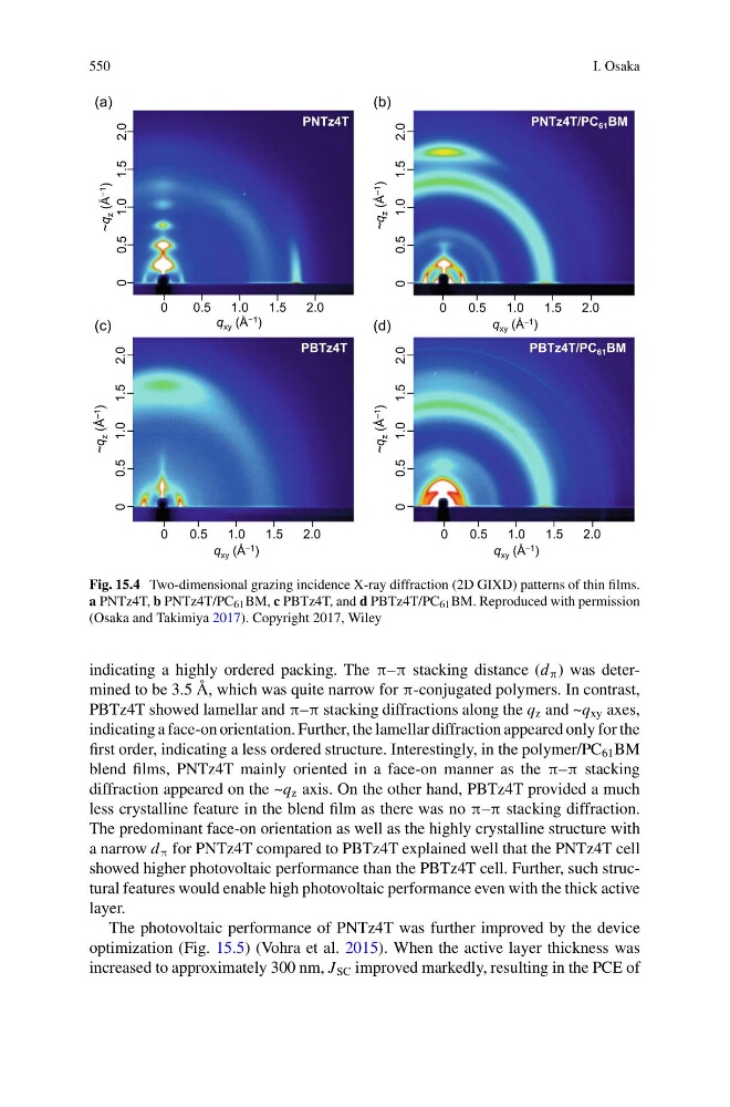
Fig. 15.4 Two-dimensional grazing incidence X-ray diffraction (2D GIXD) patterns of thin films.
a PNTz4T, b PNTz4T/PC 61 BM, c PBTz4T, and d PBTz4T/PC 61 BM. Reproduced with permission
(Osaka and Takimiya 2017). Copyright 2017, Wiley
indicating a highly ordered packing. The π–π stacking distance (d π ) was determined to be 3.5 Å, which was quite narrow for π-conjugated polymers. In contrast,
PBTz4T showed lamellar and π–π stacking diffractions along the q z and ~q xy axes,
indicating a face-on orientation. Further, the lamellar diffraction appeared only for the
first order, indicating a less ordered structure. Interestingly, in the polymer/PC 61 BM
blend films, PNTz4T mainly oriented in a face-on manner as the π–π stacking
diffraction appeared on the ~q z axis. On the other hand, PBTz4T provided a much
less crystalline feature in the blend film as there was no π–π stacking diffraction.
The predominant face-on orientation as well as the highly crystalline structure with
a narrow d π for PNTz4T compared to PBTz4T explained well that the PNTz4T cell
showed higher photovoltaic performance than the PBTz4T cell. Further, such structural features would enable high photovoltaic performance even with the thick active
layer.
The photovoltaic performance of PNTz4T was further improved by the device
optimization (Fig. 15.5) (Vohra et al. 2015). When the active layer thickness was
increased to approximately 300 nm, J SC improved markedly, resulting in the PCE of
I. Osaka
Fig. 15.4 Two-dimensional grazing incidence X-ray diffraction (2D GIXD) patterns of thin films.
a PNTz4T, b PNTz4T/PC 61 BM, c PBTz4T, and d PBTz4T/PC 61 BM. Reproduced with permission
(Osaka and Takimiya 2017). Copyright 2017, Wiley
indicating a highly ordered packing. The π–π stacking distance (d π ) was determined to be 3.5 Å, which was quite narrow for π-conjugated polymers. In contrast,
PBTz4T showed lamellar and π–π stacking diffractions along the q z and ~q xy axes,
indicating a face-on orientation. Further, the lamellar diffraction appeared only for the
first order, indicating a less ordered structure. Interestingly, in the polymer/PC 61 BM
blend films, PNTz4T mainly oriented in a face-on manner as the π–π stacking
diffraction appeared on the ~q z axis. On the other hand, PBTz4T provided a much
less crystalline feature in the blend film as there was no π–π stacking diffraction.
The predominant face-on orientation as well as the highly crystalline structure with
a narrow d π for PNTz4T compared to PBTz4T explained well that the PNTz4T cell
showed higher photovoltaic performance than the PBTz4T cell. Further, such structural features would enable high photovoltaic performance even with the thick active
layer.
The photovoltaic performance of PNTz4T was further improved by the device
optimization (Fig. 15.5) (Vohra et al. 2015). When the active layer thickness was
increased to approximately 300 nm, J SC improved markedly, resulting in the PCE of